Table of Contents
Patient Geometry
Patient / External Structure
The Patient or External structure is one of key importance in Astroid. This structure is used to define the extents of the dose calculation process. This includes the extents of the dose grid, as well as useful area of the CT images for the purposes of Relative Stopping Power conversion. Planners should be aware that all area outside of the External contour is considered to have an RSP value of 0.001 (air). As a result please ensure that any devices that need to be considered in the calculation such as: patient immobilization or positioning devices or the couch are contoured as part the external contour if they will be present during treatment and may impact the delivery beams. Please note in the example below how the planner included the head holder, mask, and S-frame as part of the External contour so that all of these devices will be included in the dose calculations. The couch was safely excluded in this example because no “through couch” beams were going to be used in this treatment. This “air” override is applied BEFORE any manual user overrides are applied.

Structures
Within Astroid the planner has the ability to create additional structures that may be needed when building a treatment plan. The Astroid Planning App allows for new structure creation using modifications of existing structures only. These modifications include boolean combinations, expansions/contractions, rinds, and clipping (i.e. splitting by a plane).
General Structure Options
- Type: Set the type of the new structure (Target, OAR, Avoidance, etc)
- Type may be left blank to allow it to be “inherited” from the type of the base structure
- Color: Display color for the new structure
- Description: Optional, user specified text describing the new structure
Structure Geometry Types
The following is a detailed explanation of each of the structure geometry functions that may be used to create or edit structures within Astroid.
Combination
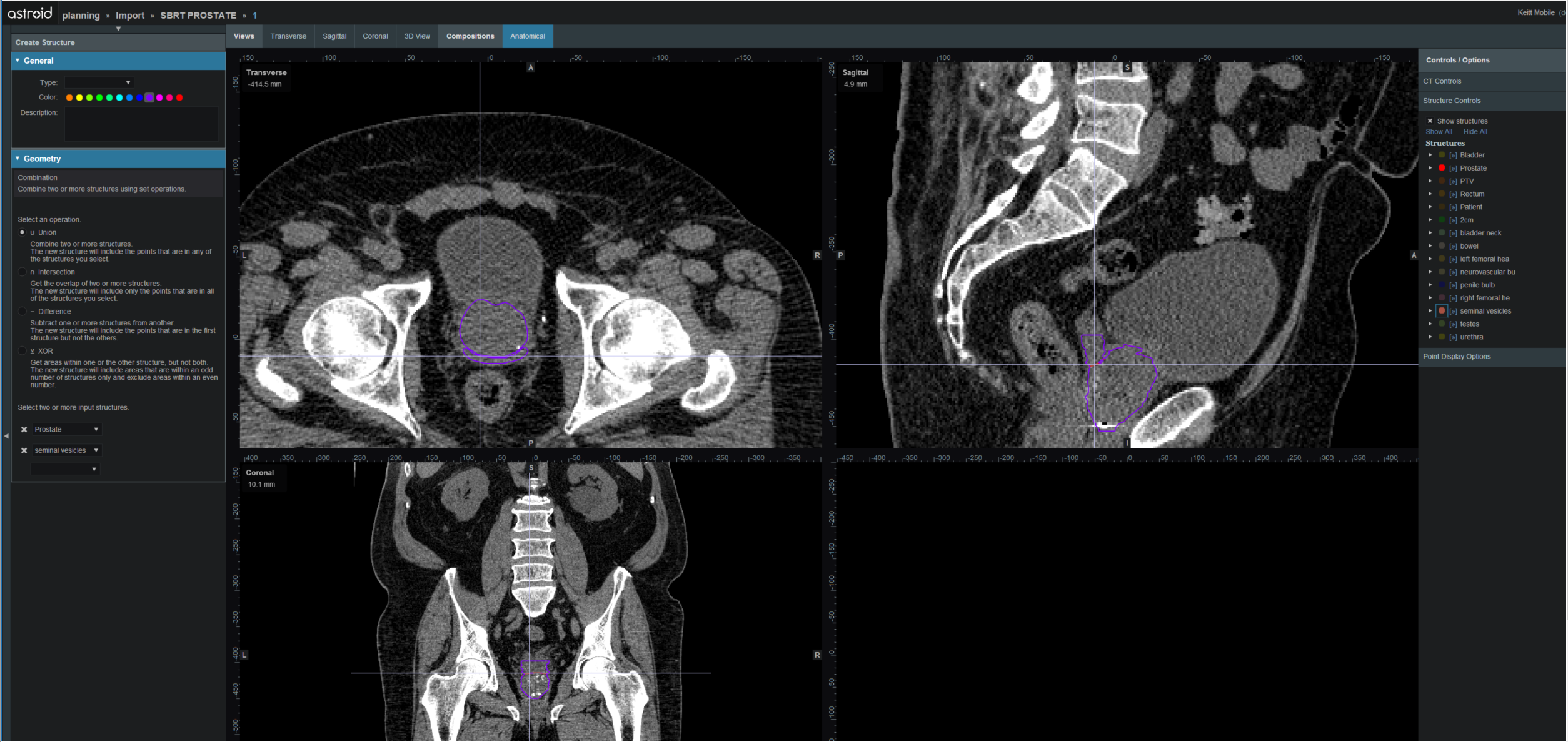
Allows for the combination of two or more structures using set (boolean) operations. The planner must choose which type of set operation they desire to create the new structure.

- Union - Combine two or more structures. The resulting new structure will contain the points that are within ANY of the selected structures. Structures are selected from a series of simple drop down menus. Refer to this union example for a sample of a union structure being created.

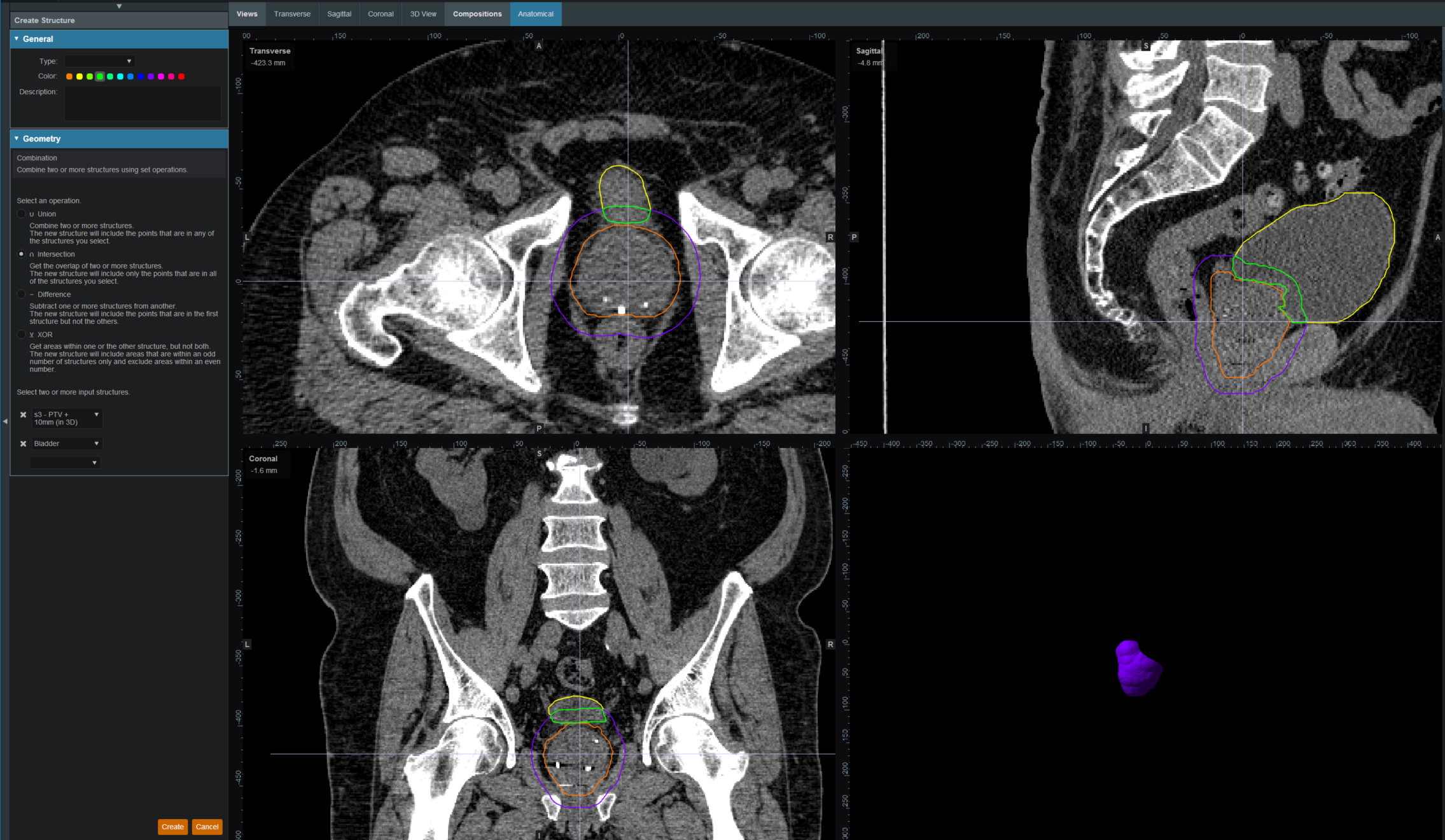
- Intersection - Use only the overlap of two or more structures. The resulting new structure will include only the points that are in ALL of the selected structures. Structures are selected from a series of simple drop down menus. Refer to this intersection example for a sample of a intersection structure being created.

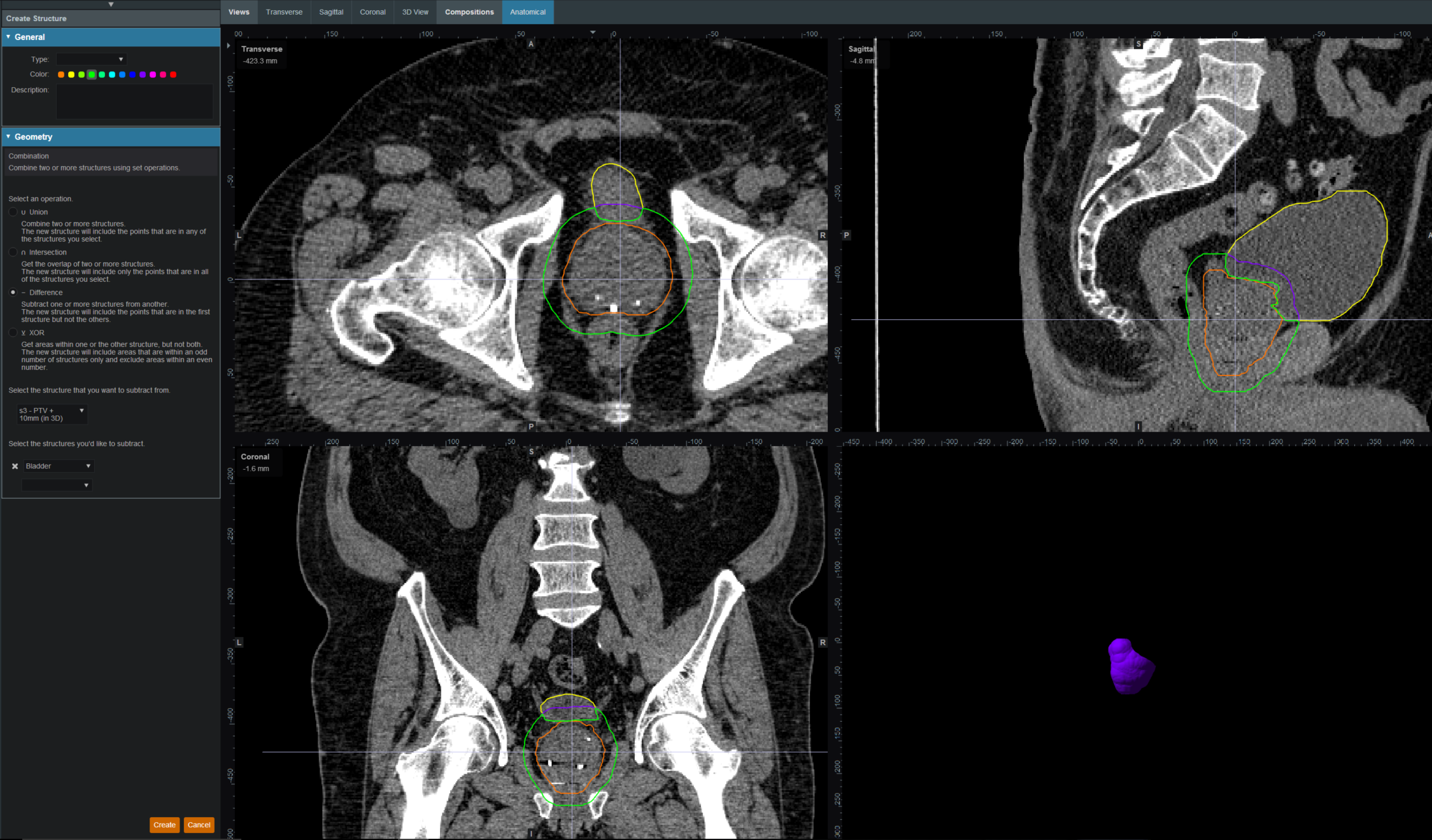
- Difference - Subtract one or more structures from a base structure. The resulting new structure will include the points that are in the first structure but not the others. The base structure is selected from the first drop down. The structures to subtract are then selected from the next series of simple drop down menus. Refer to this difference example for a sample of a difference structure being created.

- XOR (Exclusive OR) - Combine two or more structures with exclusivity. The resulting new structure will include areas that are within an odd number of structures only and will exclude areas that are within an even number of structures. Two or more structures need to be chosen from the drop down to create the new structure. The shaded areas in the examples below show the new structure and demonstrate the XOR functionality. The non-shaded areas would be excluded from the new structure.


Expansion
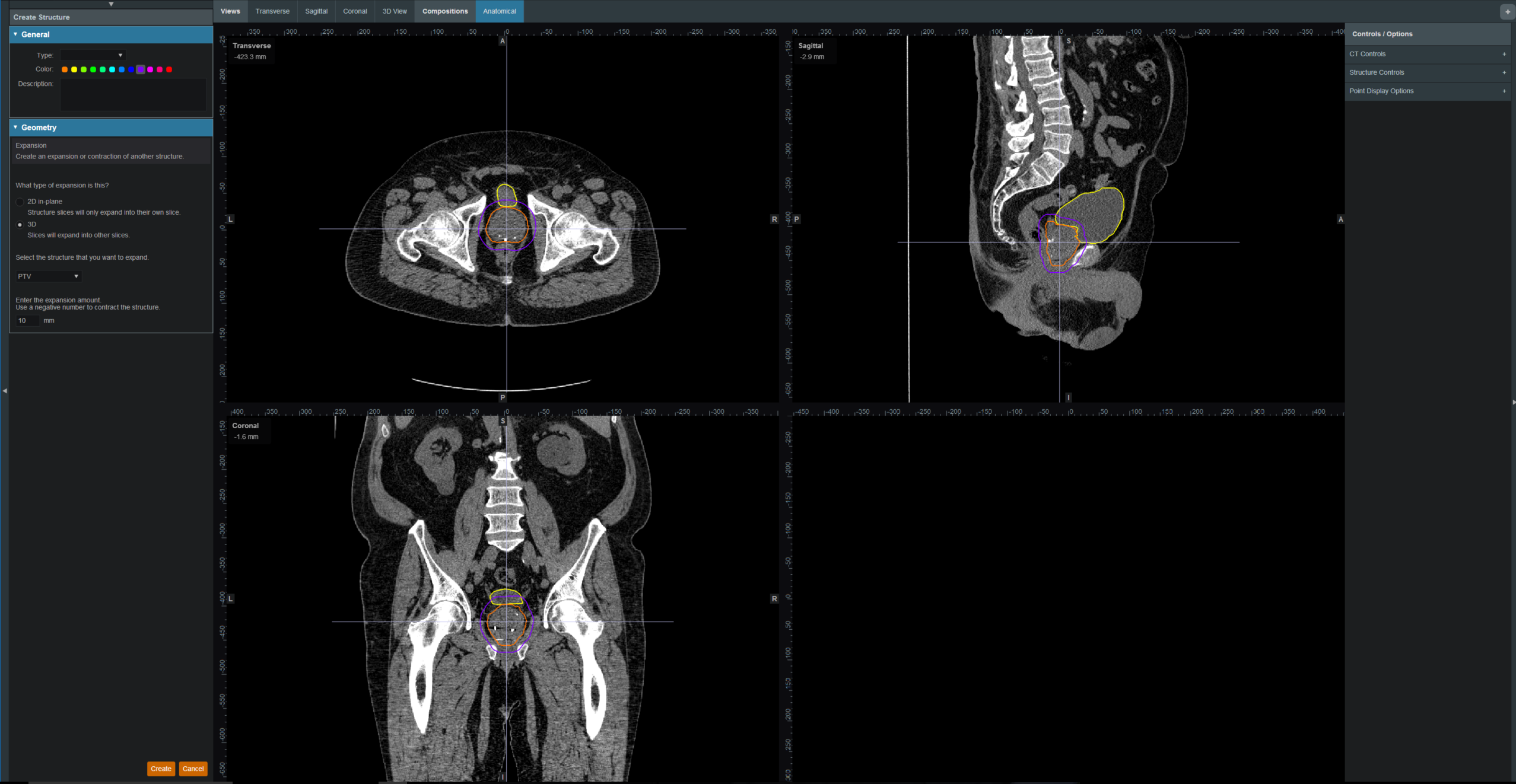
Allows for creation of a new structure as an expansion or contraction of an existing structure. The base structure is selected from a simple drop down menu. An expansion is performed by entering a positive number for the expansion amount. Conversely, a contraction is performed by entering a negative number for the expansion amount. Structures may be expranded in two dimensions (structure will only expand/contract within its original slice planes) or three dimensions (structure will expand onto other slices as a true 3D expansion). Please note that the resulting structures are still slice based entities, therefore an expansion by an amount less than a single CT slice thickness may not result in the structure expanding out to additional slices. Refer to this expansion example for a sample of an expansion structure being created.

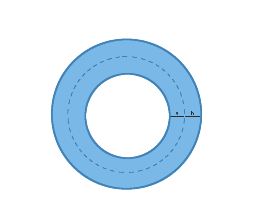
Rind
Allows for creation of a new structure as a thin ring around the surface of an existing structure. The base structure is selected from a simple drop down menu and then both an inner margin and outer margin are specified. Inner margin is the thickness of the ring toward the inside of the existing base structure. Outer margin is the thickness of the ring outside the existing base structure. Negative margins are not permitted, although zero is permitted for either value, allowing for the creation of one-directional rinds. It should also be noted that the resulting rind structures are still slice based entities, therefore rind thicknesses may not be fully uniform at the superior and inferior ends, as contours are limited by the CT slice positions. Refer to this rind example for a sample of a rind structure being created.

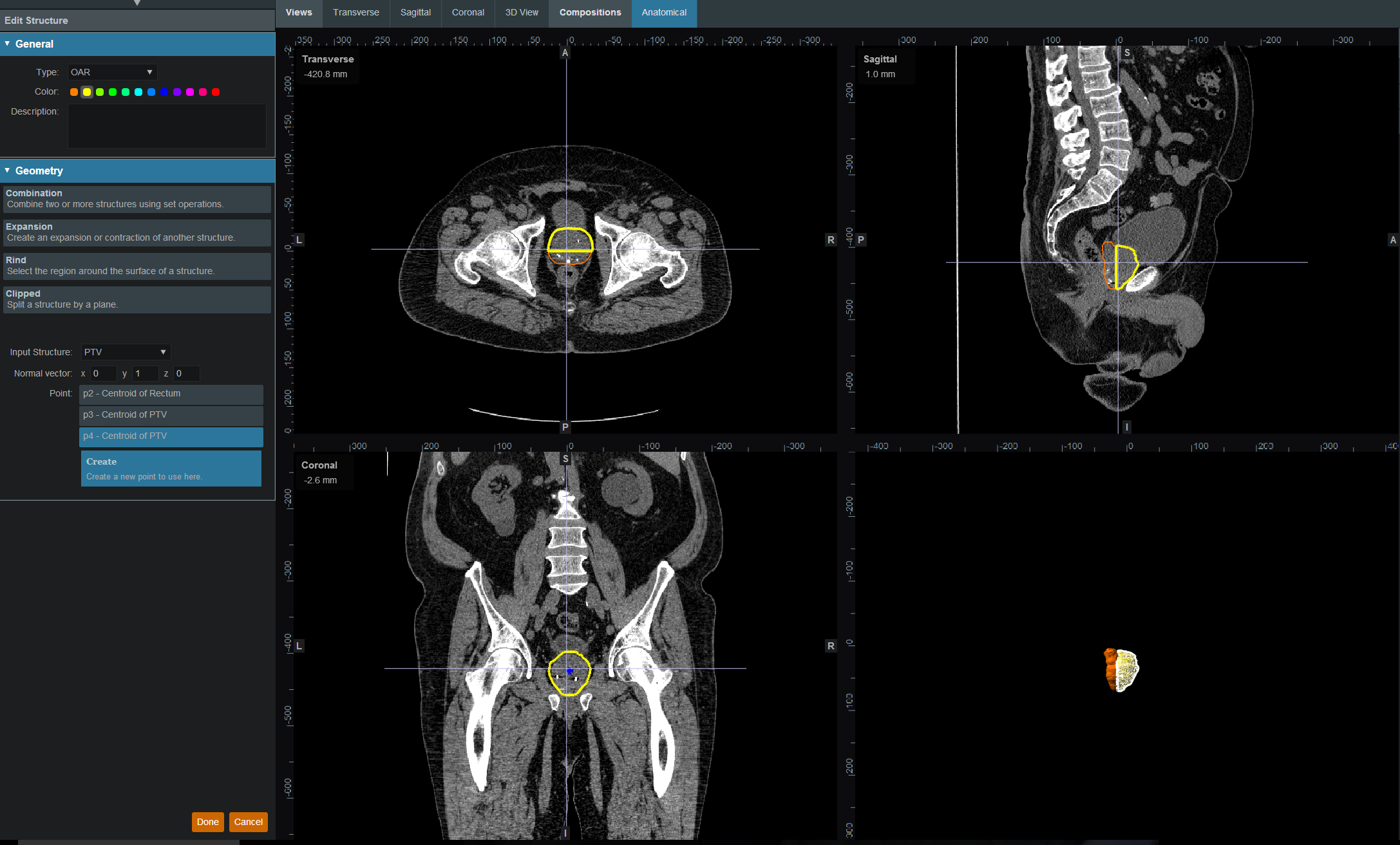
Clipped
Creates a new structure by splitting an existing structure by a user defined plane (and discarding the portion on the positive side of the plane). Any existing structure may be selected for splitting from a simple drop down menu. The split plane is defined by a single point and a normal vector pointing away from the portion of the structure that will be kept. The normal vector is defined by its three direction components XYZ and the point may be selected (or created) from the available point list menu. The XYZ normal vector directions refer to patient coordinates so that X is left-right, Y is ant-post, and Z is inf-sup (note: if the “wrong” side of the structure is removed, simply reverse the direction of the normal vector by changing the sign of each XYZ value). Refer to this clipping example of a clipped structure being created.

Working with Structures
This section walks the user through the creation of a of a new planning structure (an expansion structure is used herein for illustration purposes).
- Open the Patient Geometry block
- This will open the patient Structures list
- Click the Create New Structure button at the bottom of the list
- Next, choose the Type of structure that should be created from the drop down menu at the top (or leave this blank to “inherent” the type from the base structure)

- Change the Color and enter a Description if desired
- Then, select the method of creation desired for the new structure: Combination, Expansion, Rind, or Clipped (see above for details about each method)
- Choose the required structures and enter any other required information for this method and then click Create to complete the new structure
- For this expansion structure, the base structure and the expansion amount are all that is required
- Once a structure has been created, it can be edited, cloned, or deleted by clicking on the structure and then clicking on the appropriate button

- Note that when editing a structure, only simple options are immediately presented to the user, if further editing of the structure is needed, simply click on more options to open the full structure editing task which allows for editing of all structure options


Points
Within Astroid the planner has the ability to create additional points that may be needed when building a treatment plan. These points include Isocenter, Point of Interest (POI) and Localization points.
General Point Options
- Type: Set the type of the new structure (Isocenter, POI and Localization)
- Type may be left blank to allow it to be “inherited” from the type of the base structure
- Color: Display color for the new structure
- Description: Optional, user specified text describing the new structure
Working with Points
- Open the Patient Geometry block
- Click the Create New Point at the bottom of the Patient Geometry box
- Next, choose the Type of point that should be created from the drop down menu at the top
- Change the point Color and enter a Description if desired
- Next choose the point location- Centroid or Explicit
- Centroid will place the point in the center of the structure chosen from the drop down list at the bottom of the Geometry box

- Explicit allows the user to place a point anywhere within the patient. The user will may enter the point coordinates in the XYZ axis (The XYZ normal vector directions refer to patient coordinates so that X is left-right, Y is ant-post, and Z is inf-sup) or may simply click and drag on a display to select the location of the point.


