Table of Contents
Electron Beams
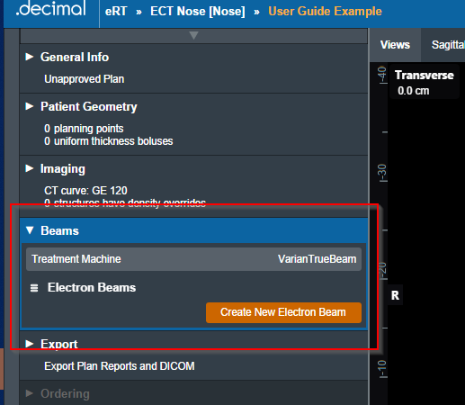
In the Beams block users can manage all the beams, as well as any blocks, boluses, or other devices included with them, included in the plan. In addition, new beams can be created and added to the plan from here.
Note: The Beams block will be disabled if no machine or CT curve exists in the site configuration.
Managing Existing Beams
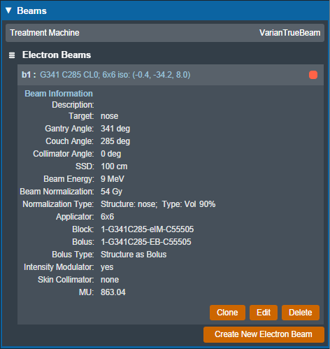
The electronRT application will list all beams included in a plan. For each of these existing beams, selecting it will show a summary of the details for that beam. Additionally, as shown below, the user has three options for the selected beam:
- Clone: Create an identical copy of the selected beam and add it to the plan.
- Edit: Open the editing dialog to change any editable property of the beam.
- Delete: Remove this beam from the plan.
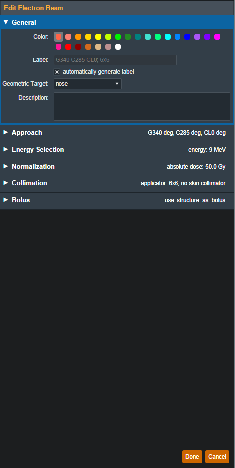
The editing dialog allows the user to edit any property of the beams that is defined in the “Structure of a Beam” section below. All changes made in this section will be saved to the beam once the user selects “Done”.
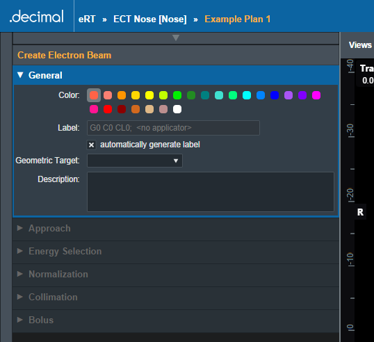
Creating New Beams
Selecting “Create New Electron Beam” directs the user to a similar section as editing an existing beam with the exception that some blocks are disabled until prior required steps are completed. An in-depth explanation of each of these sections is defined in the “Structure of a Beam” section below.
Structure of a Beam
General
The “General” Section of the Beams block allows the user to set the following fields for the beam:
- Color: Sets the color for this beam, this is used for displays, graphs and beam lists in the User Interface.
- Label: Sets the Label (name) of the beam. By default, the “automatically generate label” option is enabled for new beams, un-selecting this option allows the user to manually edit the beam label.
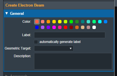
- Geometric Target: Sets the target structure for this beam. Only “target” type structures will be available for selection in this list. The following criteria must be met for structures to be able to be selected as a beam target:
- Structures flagged in the imported DICOM RT Structure Set with the following RT ROI Interpreted Type (3006,00A4):
- CTV
- GTV
- PTV
- CONTROL
- Structures with the following within their name:
- “ctv”
- “gtv”
- “ptv”
- “target”
- Refer to Editing a Course Structure to change a structure type
Once a geometric target has been set, the application will attempt to automatically calculate and set:
- Beam Approach: A computed best guess at an orthogonal beam approach. The gantry or couch angles will be snapped to 0 degrees if:
- The gantry angle is less than 5.0 or greater than 355.0 degrees
- The couch angle is less than 10.0 or greater than 350.0 degrees
- Beam Energy: The minimum commissioned energy with an R90 large enough to reach the deepest portion of the distal surface of the target.
- Beam Normalization: If a matching normalization template is found this will automatically be applied.
- Block Size: The smallest fitting block size enabled for the selected treatment machine.
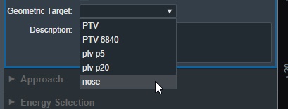 Fig. 6: Geometric Target Options
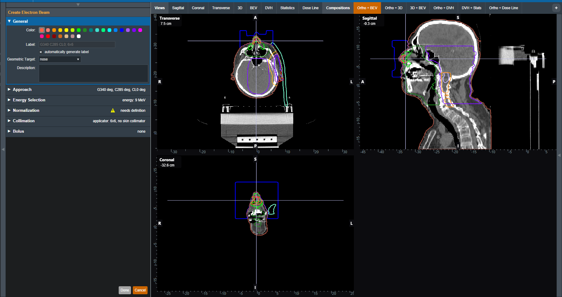 Fig. 7: UI updated with the new target
Once the beam has a color, label, and target the user will be able to move on to the next block in the beam creation if this is a new beam.
Approach
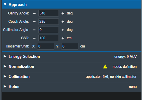
The Approach block is where the user can control the direction and position of the treatment beam. Here the user can set:
- Gantry Angle: Sets the Gantry angle for the beam.
- Couch Angle: Sets the Couch angle for the beam.
- Collimator Angle: Sets the Collimator angle for the beam.
- SSD: Sets the Source-to-surface distance.
- Isocenter Shift: Shifts the beam's isocenter. This shift is within the beam space coordinate system where the SSD is the beam “Z” shift. This can be used to manually shift a beam based on the center of the target.
As the values are set and changed in the “Approach” Block you should see the image of the beam update in the UI.
Note: If the combination of approach settings cause a collision between the applicator and the patient, you will receive a warning and the beam will be unable to be created/saved until the collision is cleared or the warning is specifically overridden.
Energy Selection
In this block the user can select the treatment energy for the beam. Users are able to set:
- Planning Isodose: The user can set the planning isodose level (relative dose) for the distal edge of the selected target.
- Beam Energy: The user is able to select an energy for this beam. This list of energies is derived from the machine data in the site configuration.
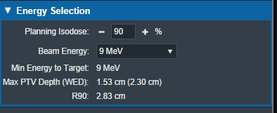
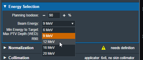 Fig. 9: Energy Selection Block
This block also displays the following values that are calculated and are not editable.
- Min Energy to Target: The minimum energy necessary to reach the entire selected target.
- Max PTV Depth (WED): The maximum physical depth (and water equivalent depth) to the distal target surface.
- R##: The computed beam range at the Planning Isodose level (range = depth of the point on the PDD at the Planning Isodose for a beam at the selected energy and specified field size).
Electron Beam Normalization
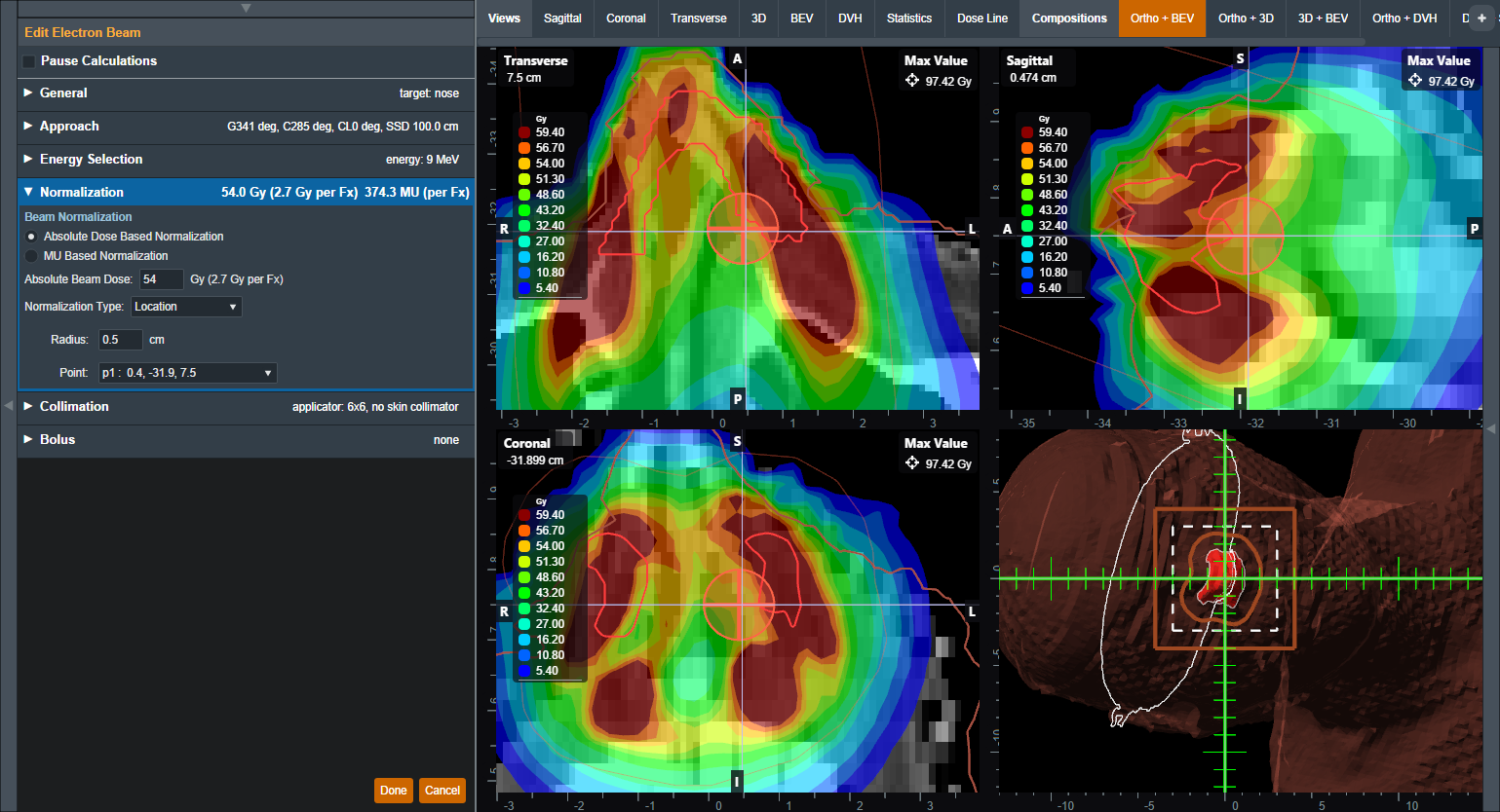
In this block the user can specify how the electron beam will be normalized. Absolute dose based normalization can be selected to scale the computed relative dose (%) to absolute (Gy) dose.
If the Course is assigned a treatment site with a beam normalization template and the the selected geometric target is one of the prescription structures, the normalization will be set according to the template in the treatment site. If the the geometric target is not a prescription structure, the absolute dose value must be set by the user. Refer to Editing the Site Settings to set a beam normalization template.
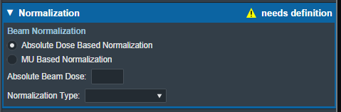 Fig. 11: Absolute Dose Beam Normalization
If MU dose conversion tables exist in the machine selected for the plan, MU based normalization can be selected to scale the relative dose based on a user specified MU value per fraction. In this case, the absolute beam dose value is calculated based on the given MU value per fraction. MU dose conversion data tables can be imported in the Site Configuration Machine Settings.
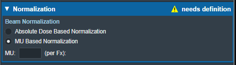 Fig. 11: MU Based Beam Normalization
The eRT application provides the following options for absolute dose based normalization:
- Location: Normalize the dose to a small spherical volume surrounding a specific point.
- Users are able to specify the sphere's center point and radius.
- The average Given Dose within the specified sphere is computed and set to the Absolute Beam Dose value when normalizing the beam.
- The normalization sphere will be shown in the sliced views when this location-based normalization option is used.
- Structure: Normalize the dose to a structure from the imported DICOM Structure Set. The following structure options are available to normalize dose to a structure:
- Min: The minimum Given Dose within the specified structure is found and this value is set to the Absolute Beam Dose value.
- Mean: The average Given Dose within the specified structure is computed and this value is set to the Absolute Beam Dose value.
- Vol: The Given Dose covering the specified fraction of the structure is computed and this value is set to the Absolute Beam Dose value.
- Isodose: Set a specific Given Dose value to the Absolute Beam Dose value.
Collimation
Here the user can add or edit an electron block for this beam. The user also has the option to add a skin collimator in addition to an electron block. More details on electron blocks can be found in the Electron Block Creation section below. More details on skin collimator creation can be found in the Skin Collimator Creation section below.
Bolus
Here the user can add or edit a bolus for this beam, more details on bolus creation can be found in the Electron Bolus Creation section below (Intensity Modulators can also be added here).
Dose Calculation
The eRT application automatically runs the dose calculation anytime the beam configuration is altered by the user, there is no need to explicitly compute dose. Whenever a dose is displayed on the screen, you can be sure it is the dose corresponding to the currently specified beam information (there may be a slight 2-4 second delay after modifying a beam parameter in which time the prior dose result is still visible, this is to ensure the user has finished their current edits and avoids starting extra, unwanted dose calculations).
Please read the Dose Calculation Algorithms page for a complete description of the dose calculation algorithms used within the eRT application.