
Table of Contents
Application Usage and Features
Launching ElectronRT
In order to Launch the decimal ElectronRT app you must use the decimal Launcher to authenticate and open your desired application.
NOTE: You will need your .decimal Direct user Log in.
- Download and install the decimal Launcher.
- Log in with your .decimal credentials.
- Find decimal ElectronRT and download/launch the application.
For further instructions please refer to the decimal Launcher User Guide.
DICOM Patient Import
In order to begin planning in the decimal ElectronRT App you must first have patient imaging captured and structure geometries defined. This information is brought in the ElectronRT App by importing DICOM CT and Structure Set files.
Note: DICOM patient import will be disabled until the organization configuration has been completed.
Default Import Directory
The default import directory can be set in the app settings by navigating to View → Settings. This directory will always be the default directory when importing a patient. Users can then further refine the import folder as needed starting from this default level.
Importing a New Patient
The ElectronRT application has two methods for importing new DICOM patients: 1) Manually browsing for local files and 2) setting up a DICOM receiver to accept and import DICOM patients. Refer to the sections below for details on each option.
Local File Import
If you have a set of Ct Images and structures you can import them directly into a new patient through the “Import Patients” menu.
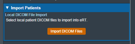 Fig. 1: Import in the Main App Page
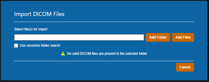 Fig. 2: Import Directory Input
The Import DICOM Files option allows you to either browse your computer or copy the path to the folder that contains the CT images and structures you wish to import. The following options are available for browsing for local files:
- Add Folder: Browse for an entire folder of DICOM files to import into a patient
- Use recursive folder search: This option can be selected prior to adding a folder to reclusively search and add all DICOM files within the selected folder and all sub-folders.
- Add Files: Browse for individual DICOM file(s) to import into a patient. Note: this option does not make use of the recursive folder search option.
A list of selected DICOM files for import will be displayed and you can choose to add more files for the selected patient or remove any files as desired.
Refer to the Processing Imports section once files have been selected to import.
DICOM Receiver Imports
Users can install and configure the ElectronRT DICOM Receiver to receive and save patients for seamless importing into the ElectronRT application.
Users can then specify a DICOM Import Monitoring Directory within the Site Configuration's DICOM Settings block that corresponds to the storage_location field set for the ElectronRT DICOM Receiver. Once the receiver and monitoring directory have been setup and configured, any DICOM patients sent to the ElectronRT DICOM Receiver will automatically show up within the Import Patients display as shown in figure 3.
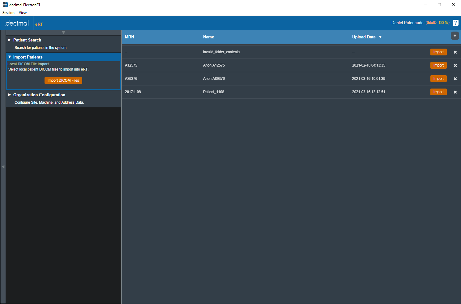 Fig. 3: DICOM Receiver Patients
Each patient received from the ElectronRT DICOM Receiver can be imported or removed from within the eRT Import Patient block.
Refer to the Processing Imports section once a patient has been selected for import.
Processing Imports
Clicking the Import button will start processing the selected files.
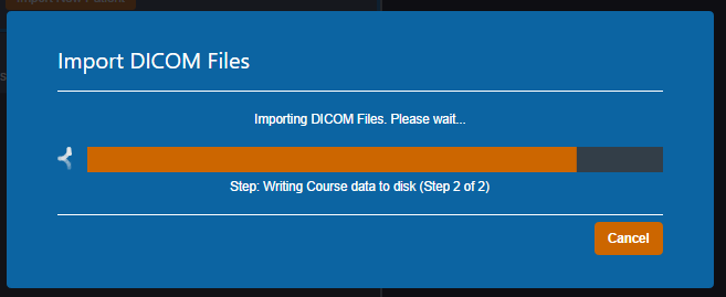
If there are no Errors while importing you will be taken to a confirmation page for your import.
If there are errors, please refer to the Common Errors section below for further details.
Importing DICOM Plans
Users have the option to import DICOM Plan files in addition to CT images and structure sets. For now, only electron plans can be imported into the decimal ElectronRT app. When importing a new patient, the DICOM plan file must have the proper UIDs that reference the structure set in order for the plan to be successfully imported. An imported plan will appear under the course of the new patient and will be marked as imported.
Refer to the Imported Plans section for more information on imported plans.
Common Errors
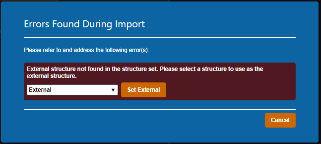
Missing/Undefined External Structure
If the imported DICOM Structure Set does not have a structure flagged as RT ROI Interpreted Type (3006,00A4) EXTERNAL you will be directed to specify the external patient structure before the import resumes. The patient external structure must be set to the defining boundary of the patient's outer surface, and not a rind skin structure.
Note: You will be warned if the selected external structure is not the structure with the largest volume. This is to prevent incorrect structure selection. For example, when a 'External' and 'Skin' structure both exist, and the 'Skin' structure is a rind, if the user selects the 'Skin' structure, the warning will state the 'External' structure has a larger volume, since that's the correct representation of the patient structure needed for the ElectronRT App.
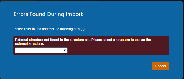 Fig. 6: Missing External Error
The drop down menu will have a list of the structures in the imported set. You will be able to select one as the external for this course then confirm your choice by pressing “Set External”.
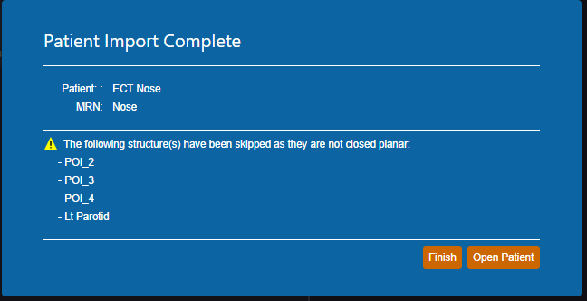
Structures Skipped During Import
Structures can be skipped during Structure Set import if the structures meet the following criteria:
- Non closed planar (e.g.: points or structures where slices are not fully closed)
Structures that are skipped will be denoted at the end of the DICOM import as shown in figure 8.
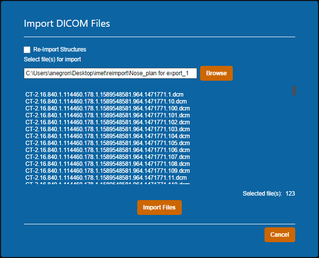
Importing an Existing Patient
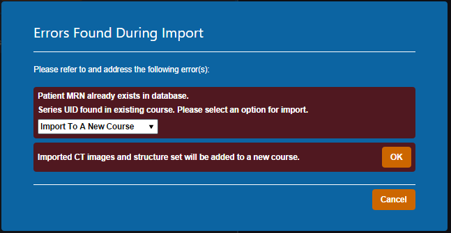
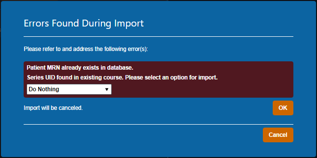
If the files you have selected to import coincide with the MRN of a patient that already exists in the database you will receive this error.
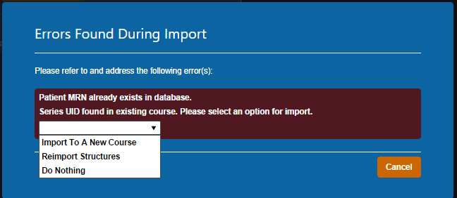 Fig. 9: Existing Patient Error
You have three options provided to resolve the error:
- Import to a New Course
- Re-Import Structures
- Do Nothing
Import to a New Course
Importing to a new course will simply complete the import with the app creating a new course for this patient using the new imported files (note this option will not affect any existing courses or plans for the patient).
Re-import Structures
Re-Importing structures can be used if your goal is to update or add structures to an existing patient Course.
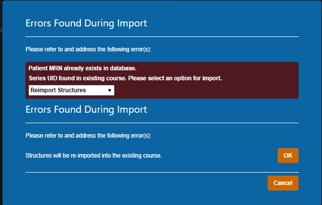
After selecting this option, you will be presented with a list of the structures in the import.
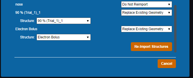
For each you may select one of three options:
- Do not Re-import: Skips this structure for the re import.
- Replace existing geometry: Replaces the existing structure in the current Course with the imported one.
- Import as new structure: Imports the structure to the Course as a new structure while not affecting the existing one and allows the user to specify a new name for the new structure. If the structure does not exist currently it creates it as normal.
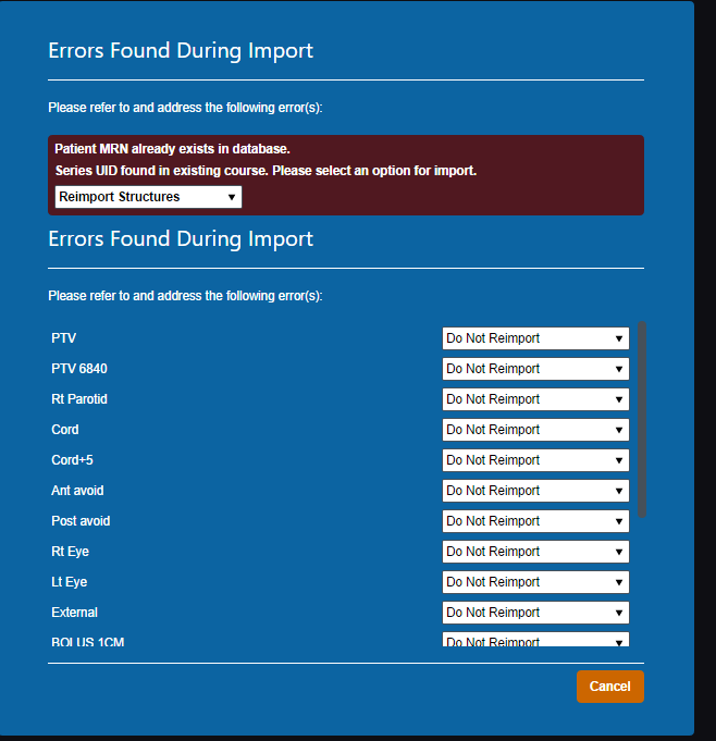 Fig. 12: Re-Importing Structure List
Once you have made your decision for each structure you must select “Re-Import Structures” to finalize your changes.
Do Nothing
Patient Courses
Once you have a Patient imported you will need to set up a Course for that patient before being able to create any treatment plans. A Course is used to define the patient's anatomy (e.g.: a single DICOM Structure Set and CT Image Set).
The Course Information settings decided here will be inherited by any plans in this Course and can be edited in the Course UI later to update all non-approved plans within the Course.
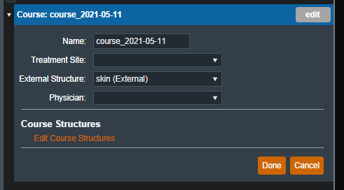
Course
In the Course block you can set the following fields:
- Name : Initially this label is automatically generated but can be changed as desired.
- Treatment Site : This list is taken from your site settings, you are able to add or remove treatment sites from the Site Configurations block. For more information please refer to the Site Settings.
- External Structure: The external structure will be automatically determined based on DICOM structure types during import. You are also able to override the initial selection with any other structure in the structure list if desired.
- Physician : This list is taken from your site settings, you are able to add or remove physicians from the Site Configurations block. For more information please refer to the Site Settings.
Course Structures
Certain tasks within eRT require structures to be set to a specific type, and their type is set based on the DICOM RT ROI Interpreted Type (3006,00A4) tag during initial patient import. The Course Structures user interface allows users to change the type of each structure within the patient course.
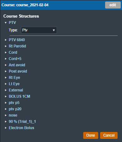 Fig. 17: Editing Course Structures
Note: The RT ROI Interpreted Type (3006,00A4) tag is optional in a DICOM RT Structure Set. As such, the structure type drop down may be empty if no structure type was specified in the imported DICOM files.
Electron Treatment Plans
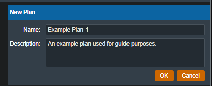
Once the patient has a course with a valid prescription, a plan can be created. When adding a new plan to a patient, the user will be prompted to add a name and an optional description for the plan.
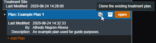
From the Patient Overview, the user can choose to clone an existing plan. As the cloned plan will be a copy of the original plan (except for the plan name and if cloning an approved plan, the clone will be unapproved), the user should name the cloned plan appropriately to avoid confusion.
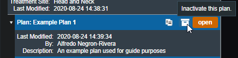
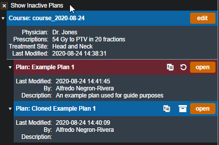
The user may also choose to make an existing plan inactive. Doing so will remove (hide) the plan from the Patient Overview. The user can view inactive plans and have the option to make them active again if they click the “Show Inactive Plans” check box.
Approved Plans
Refer to Plan Approval for information on approved plans.
Plan History
The plan history UI exists within the General Info block of the plan overview. This interface allows users to view the details of all changes to a treatment plan, view the plan as it was at the time of each revision (as read-only), and make any past revision “active” as the current revision (i.e. restore a plan to match the selected revision).
Refer to figure 22 below for a detailed explanation for each of the Plan History features.
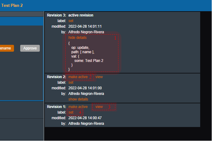
Plan History UI Explained
- [1] Show/Hide Details: Provides details of the changes for each revision. Currently the revision comparison shows a textual comparison between the selected revision and the immediately preceding revision.
- For example: the details shown for Revision #3 tell us that the Update operation was performed on the variable name to the value Test Plan2. Or in other words, the plan's name was updated to 'Test Plan2'.
- [2] Make Active: Makes the desired selected revision the current active revision of this plan (i.e. reverts the plan to match this revision).
- [3] View: Opens the selected revision for review by the user in a read-only view mode.
- [4] Set: Sets the revision label to a user-provided value.
Imported Plans
After a DICOM plan is successfully imported, it will appear under the course containing the structure set that the plan is linked to it. The plan is marked as imported in the Patient Overview.
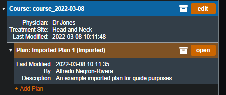 Fig. 23: Imported Plan in Patient Overview
When opening a newly imported plan, the user must first select the CT curve and treatment machine in order to view the imported plan overview.
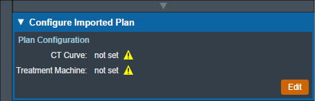 Fig. 24: Imported Plan Configuration
Unlike plans created in the decimal ElectronRT plan, users are limited in what they can do with imported plans. Users cannot add points, density overrides, or edit beams other than adding a Structure as Bolus into an imported plan. Users can approve imported plans and order devices from approved imported plans, but they cannot use QA Tools.
Packing and Exporting Plans
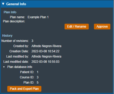
If a plan has to be sent to .decimal for the purpose of troubleshooting, the user is able to pack and export the plan into a zipped folder that can be imported into a different site while still using the data of the original site and machine. The Pack and Export Plan button found after expanding the Plan database info in the General Info block will generate the necessary zipped folder.
Only unapproved plans can be packed. If you require to pack and send .decimal an approved plan, please clone the plan and send the cloned unapproved plan to .decimal.
The resulting .zip file can be sent to .decimal to unpack and view your patient/plan to reproduce any application issues.
Note: The packed data does potentially contain PHI/PII so should only be sent to .decimal staff using secure file transfer services. The exported files are not encrypted (so that .decimal staff can re-import them), but are a non-human readable, proprietary compressed binary format.
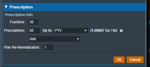
Prescription
You can add multiple prescriptions for different target structures and all of them will be applied to the treatment plan. The plan re-normalization value can be used to scale the final plan level dose.
In the Prescription block you can set the following fields:
- Fractions : This is the number of fractions over which the prescription dose will be delivered.
- Prescriptions : This is the total prescription dose value in Gy (maximum of 100 Gy) and the target structure for said dose.
- Note that at this time prescription values do not have an exact specified meaning (e.g. mean, min) as the ElectronRT application only uses these values to scale the relative dose to absolute dose in the UI. In the event of multiple prescriptions, the eRT application will use the first prescription statement to set the 100% relative dose value.
- Plan Re-Normalization : The value used to re-normalize the plan level dose.
Patient Geometry
The Patient Geometry block allows the user to add points or edit points in the treatment plan. The user may also create uniform thickness boluses that can be used by beams in the plan.
Points
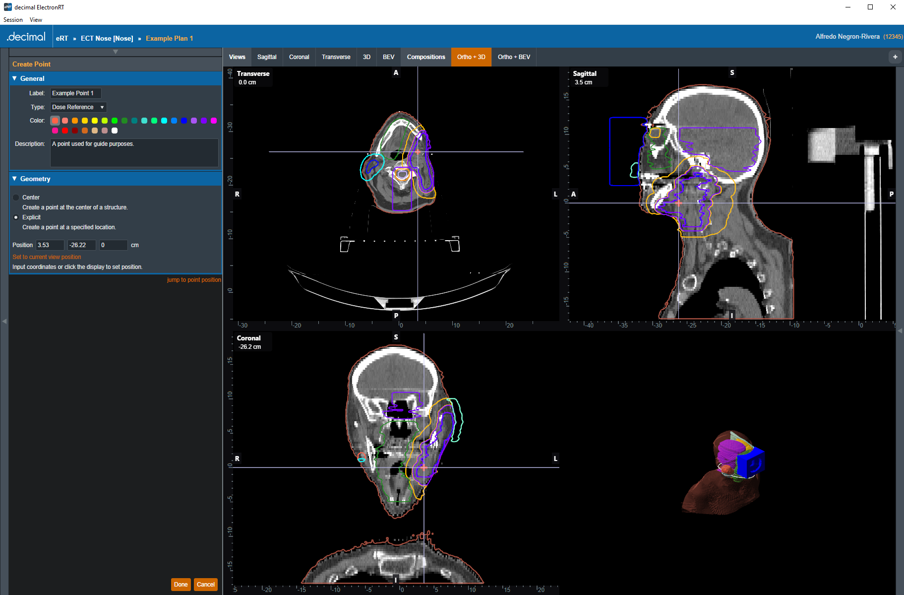
After choosing to add or edit a point, the user will be able to the edit the label, type (POI, localization, or dose reference), color, and description of the point. The geometric position of the point can be determined in one of two ways: as the center of a structure or as an explicit location.
Point Types
The types of points will determine how the point will be used in other features within the application. Below lists the supported point types and how these points are used:
- POI:
- Used for reference in the Display UI
- Localization:
- Used for reference in the Display UI
- Dose Reference:
- Used for reference in the Display UI
- Dose is shown at the specified point in the Dose Stats display view
- Will be exported to Plan and Dose QA reports along with the dose/gamma values (see the applicable report second for further details)
Point Creation
The Center option allows the user to set the point's position to the center of a structure selected from the structure set.
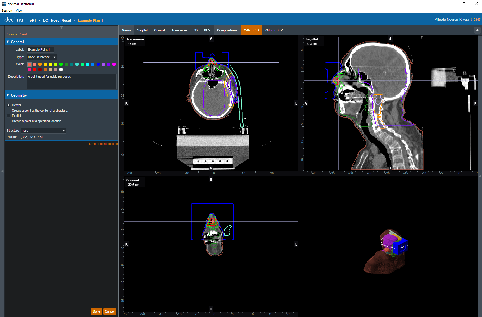 Fig. 27: Creating a Center Point
The Explicit option allows the user to set the XYZ coordinates or simply click on the CT image display to specify the point's position.
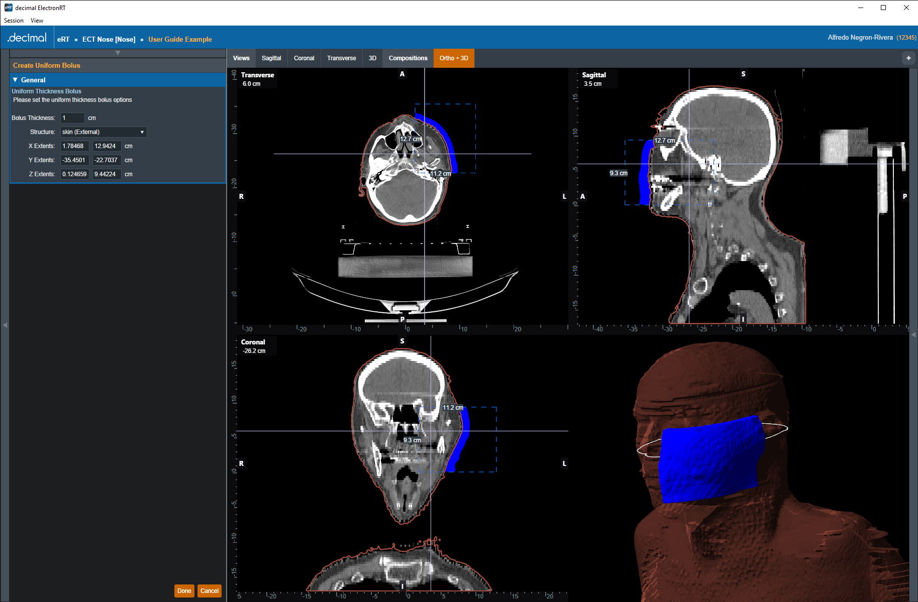
Uniform Thickness Boluses
The user has the option to add or edit uniform thickness boluses within the Patient Geometry block. When creating the bolus, the user can set the thickness and the reference structure. The shape of the bolus will be influenced by the selected structure (e.g. if the bolus will be placed on the patient's skin, the user should select the structure that corresponds to the patient's skin).
After selecting the structure, the user must specify the geometric extents of the bolus in each dimension. The user can either edit the coordinates of the extents by one of two ways:
- Manual Dimensions: directly setting the dimension values for the UTB extents box
- Display Dragging: drag the sides of the extents box shown in the CT image display.
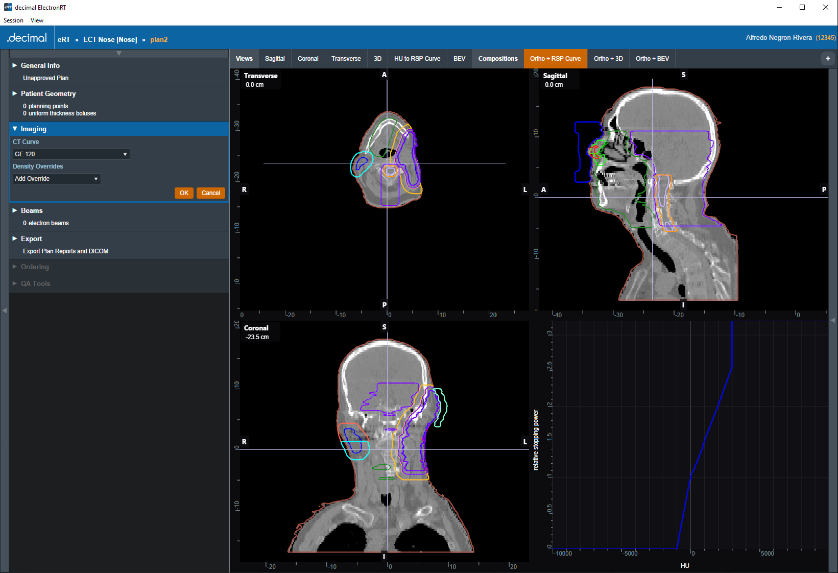
Imaging
The Imaging block allows the user to choose or change the HU (Hounsfield Unit) to RSP (Relative Stopping Power) curve to use during the planning process. The user may also specify Density/RSP overrides for existing structures in this block.
CT Curve
The user can select the HU to RSP CT curve from a list of curves that exist within the site configuration. Refer to the Site Configuration Setup for managing the list of curves. If only one CT curve exists in the site configuration, it will be automatically selected when the plan is created. The selected HU to RSP curve will be displayed in the bottom right section of the display UI.
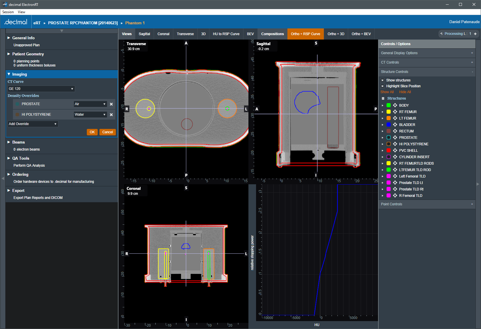
Density Overrides
From within the Imaging block users may specify density overrides for existing structures.
The materials allowed for density overrides are pre-defined within the site configuration. Refer to the Organization Settings for adding and managing the density override material list.
Density Override Order
Density overrides are applied in order from the first override in the list to the last override. Any subsequent density overrides applied after existing overrides may change previously overriden densities.
Example of Correct Density Override Order
For example, consider figure 31. The structures HI POLYSTYRENE and PROSTATE both have a density override applied.
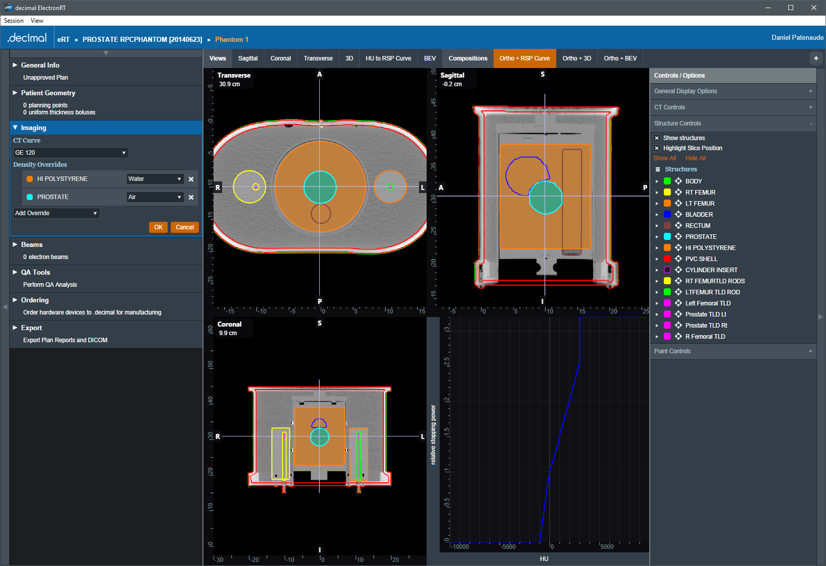
The HI POLYSTYRENE density override will be applied first and all pixels within this structure will be set to the density of 'Water'. Then the PROSTATE structure density override will be applied and all pixels within this structure will be set to the density of 'Air'. The resulting overrides can be seen in figure 32.
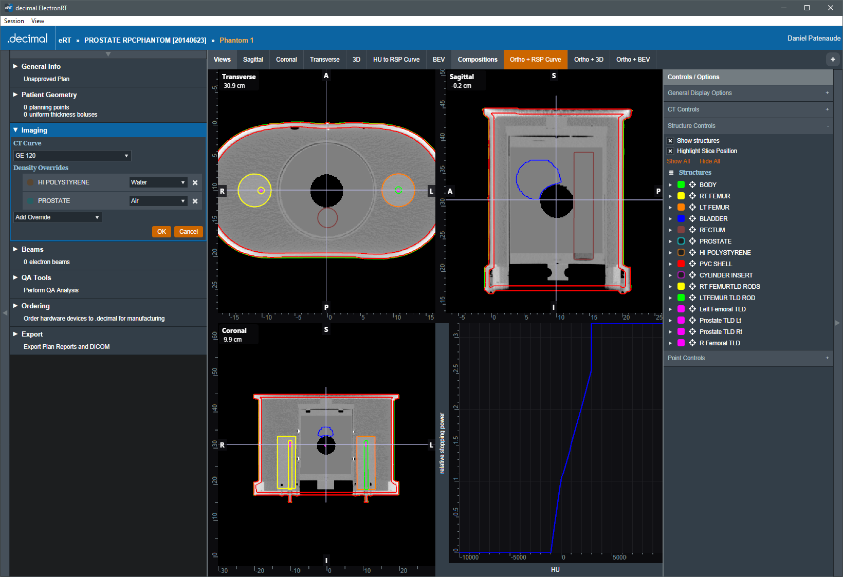
Example of Incorrect Density Override Order
For example, consider figure 33. The structures HI POLYSTYRENE and PROSTATE both have a density override applied.
The PROSTATE density override will be applied first and all pixels within this structure will be set to the density of 'Air'. Then the HI POLYSTYRENE structure density override will be applied and all pixels within this structure will be set to the density of 'Air'. The resulting overrides can be seen in figure 33. Because the larger structure's density overrides were applied last, the smaller contained structure's density overrides were lost.
Electron Beams
In the Beams block users can manage all the beams, as well as any blocks, boluses, or other devices included with them, included in the plan. In addition, new beams can be created and added to the plan from here.
Note: The Beams block will be disabled if no machine or CT curve exists in the site configuration.
Managing Existing Beams
The electronRT application will list all beams included in a plan. For each of these existing beams, selecting it will show a summary of the details for that beam. Additionally, as shown below, the user has three options for the selected beam:
- Clone: Create an identical copy of the selected beam and add it to the plan.
- Edit: Open the editing dialog to change any editable property of the beam.
- Delete: Remove this beam from the plan.
 Fig. 35: Existing Beam Example
The editing dialog allows the user to edit any property of the beams that is defined in the “Structure of a Beam” section below. All changes made in this section will be saved to the beam once the user selects “Done”.
Creating New Beams
Selecting “Create New Electron Beam” directs the user to a similar section as editing an existing beam with the exception that some blocks are disabled until prior required steps are completed. An in-depth explanation of each of these sections is defined in the “Structure of a Beam” section below.
Structure of a Beam
General
The “General” Section of the Beams block allows the user to set the following fields for the beam:
- Color: Sets the color for this beam, this is used for displays, graphs and beam lists in the User Interface.
- Label: Sets the Label (name) of the beam. By default, the “automatically generate label” option is enabled for new beams, un-selecting this option allows the user to manually edit the beam label.
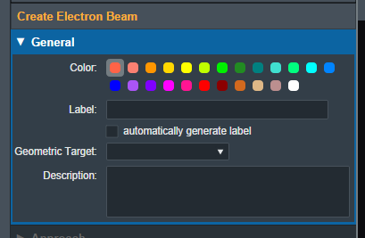
- Geometric Target: Sets the target structure for this beam. Only “target” type structures will be available for selection in this list. The following criteria must be met for structures to be able to be selected as a beam target:
- Structures flagged in the imported DICOM RT Structure Set with the following RT ROI Interpreted Type (3006,00A4):
- CTV
- GTV
- PTV
- CONTROL
- Structures with the following within their name:
- “ctv”
- “gtv”
- “ptv”
- “target”
- Refer to Editing a Course Structure to change a structure type
Once a geometric target has been set, the application will attempt to automatically calculate and set:
- Beam Approach: A computed best guess at an orthogonal beam approach. The gantry or couch angles will be snapped to 0 degrees if:
- The gantry angle is less than 5.0 or greater than 355.0 degrees
- The couch angle is less than 10.0 or greater than 350.0 degrees
- Beam Energy: The minimum commissioned energy with an R90 large enough to reach the deepest portion of the distal surface of the target.
- Beam Normalization: If a matching normalization template is found this will automatically be applied.
- Block Size: The smallest fitting block size enabled for the selected treatment machine.
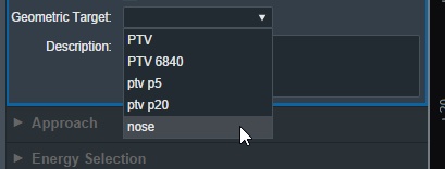 Fig. 39: Geometric Target Options
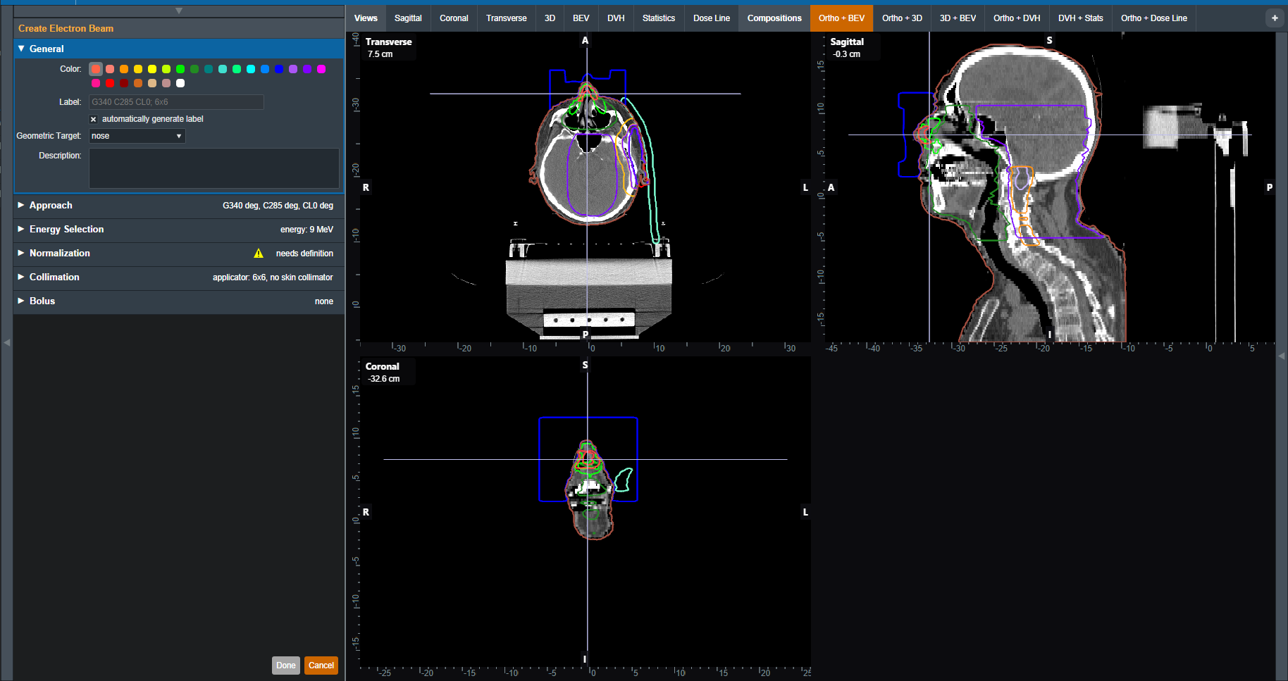 Fig. 40: UI updated with the new target
Once the beam has a color, label, and target the user will be able to move on to the next block in the beam creation if this is a new beam.
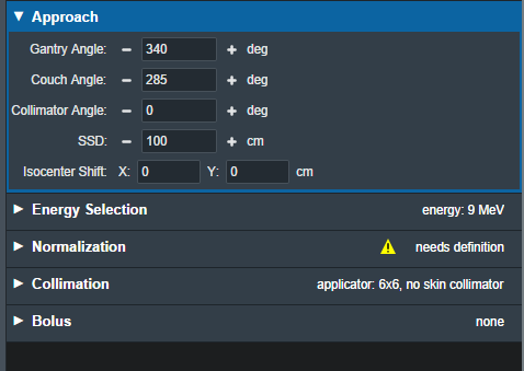
Approach
The Approach block is where the user can control the direction and position of the treatment beam. Here the user can set:
- Gantry Angle: Sets the Gantry angle for the beam.
- Couch Angle: Sets the Couch angle for the beam.
- Collimator Angle: Sets the Collimator angle for the beam.
- SSD: Sets the Source-to-surface distance.
- Isocenter Shift: Shifts the beam's isocenter. This shift is within the beam space coordinate system where the SSD is the beam “Z” shift. This can be used to manually shift a beam based on the center of the target.
As the values are set and changed in the “Approach” Block you should see the image of the beam update in the UI.
Note: If the combination of approach settings cause a collision between the applicator and the patient, you will receive a warning and the beam will be unable to be created/saved until the collision is cleared or the warning is specifically overridden.
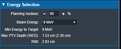
Energy Selection
In this block the user can select the treatment energy for the beam. Users are able to set:
- Planning Isodose: The user can set the planning isodose level (relative dose) for the distal edge of the selected target.
- Beam Energy: The user is able to select an energy for this beam. This list of energies is derived from the machine data in the site configuration.
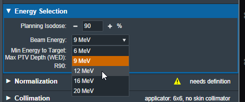 Fig. 42: Energy Selection Block
This block also displays the following values that are calculated and are not editable.
- Min Energy to Target: The minimum energy necessary to reach the entire selected target.
- Max PTV Depth (WED): The maximum physical depth (and water equivalent depth) to the distal target surface.
- R##: The computed beam range at the Planning Isodose level (range = depth of the point on the PDD at the Planning Isodose for a beam at the selected energy and specified field size).
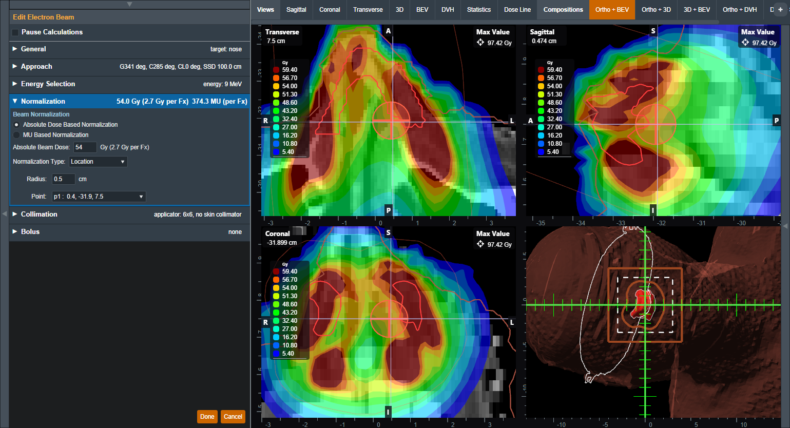
Electron Beam Normalization
In this block the user can specify how the electron beam will be normalized. Absolute dose based normalization can be selected to scale the computed relative dose (%) to absolute (Gy) dose.
If the Course is assigned a treatment site with a beam normalization template and the the selected geometric target is one of the prescription structures, the normalization will be set according to the template in the treatment site. If the the geometric target is not a prescription structure, the absolute dose value must be set by the user. Refer to Editing the Site Settings to set a beam normalization template.
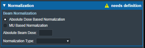 Fig. 44: Absolute Dose Beam Normalization
If MU dose conversion tables exist in the machine selected for the plan, MU based normalization can be selected to scale the relative dose based on a user specified MU value per fraction. In this case, the absolute beam dose value is calculated based on the given MU value per fraction. MU dose conversion data tables can be imported in the Site Configuration Machine Settings.
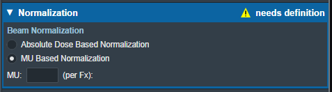 Fig. 44: MU Based Beam Normalization
The eRT application provides the following options for absolute dose based normalization:
- Location: Normalize the dose to a small spherical volume surrounding a specific point.
- Users are able to specify the sphere's center point and radius.
- The average Given Dose within the specified sphere is computed and set to the Absolute Beam Dose value when normalizing the beam.
- The normalization sphere will be shown in the sliced views when this location-based normalization option is used.
- Structure: Normalize the dose to a structure from the imported DICOM Structure Set. The following structure options are available to normalize dose to a structure:
- Min: The minimum Given Dose within the specified structure is found and this value is set to the Absolute Beam Dose value.
- Mean: The average Given Dose within the specified structure is computed and this value is set to the Absolute Beam Dose value.
- Vol: The Given Dose covering the specified fraction of the structure is computed and this value is set to the Absolute Beam Dose value.
- Isodose: Set a specific Given Dose value to the Absolute Beam Dose value.
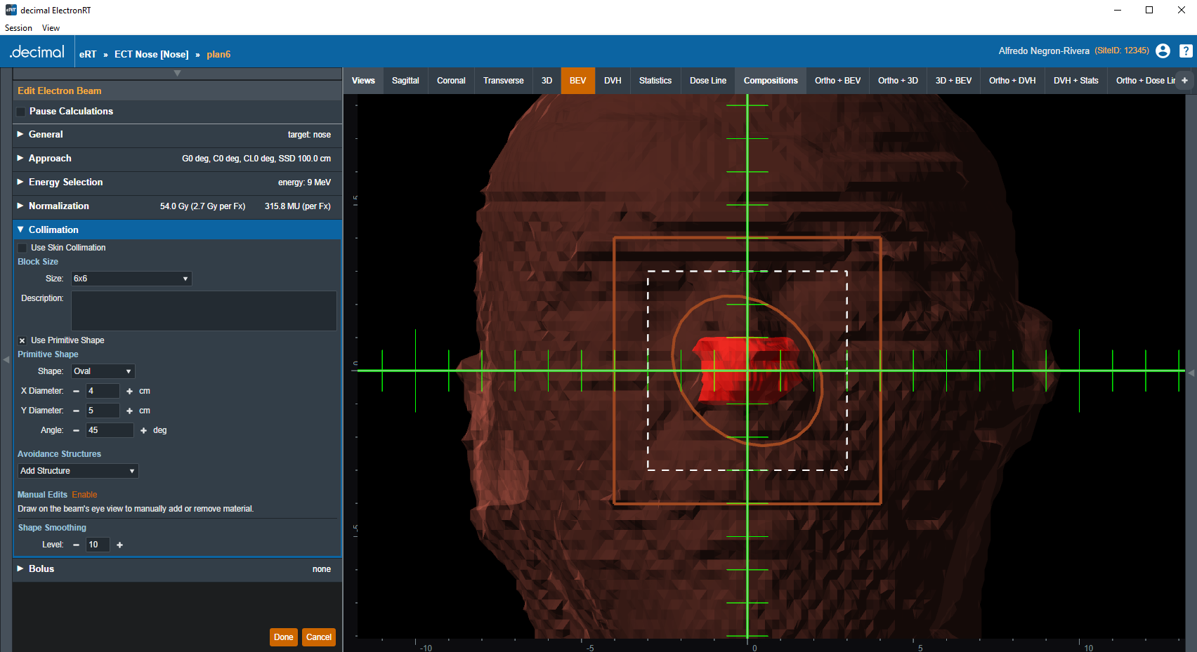
Collimation
Here the user can add or edit an electron block for this beam. The user also has the option to add a skin collimator in addition to an electron block. More details on electron blocks can be found in the Electron Block Creation section below. More details on skin collimator creation can be found in the Skin Collimator Creation section below.
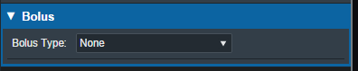
Bolus
Here the user can add or edit a bolus for this beam, more details on bolus creation can be found in the Electron Bolus Creation section below (Intensity Modulators can also be added here).
Electron Block Creation
Here the user can create and edit Electron Blocks for the selected beam as well as edit values for an existing block.

Block Size
- Size: Select the block size. The list of available block sizes is derived from the list of applicator (cone) sizes available for the selected machine. Applicator sizes can be enabled and disabled from editing the machine data in the site configuration.
Note: When first creating a beam the eRT app will auto calculate the smallest block that will fit the current aperture shape.

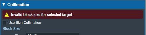
Note Selecting a block size that is too small for the aperture shape will cause an error that will not allow the creation/saving of the beam until an appropriate size is selected.
- Description: An optional description for this block used to identify it.
Target Margin
- Margin: The value (in cm) of the margin around the target structure as projected to isocenter. A negative margin can be used to specify a contraction around the beam target while positive values will cause an expansion. The default block target margin can be configured in the Site Configuration Machine Settings.
Note: The app will automatically recalculate and display changes to the block as the margin is edited.

Primitive Shape
Instead of using the geometric target, the user may use a primitive shape as the base block opening instead. The user can choose the shape (square, circle, rectangle, or oval) and the dimensions at isocenter.
Avoidance Structures
The user may select one or more structures in the structure list here to add as an avoidance structure. Avoidance structures will decrease the block opening to remove all areas within the projection of the structure.
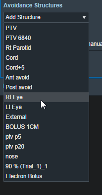 Fig. 52: Avoidance structure selection
Once the structure is selected you will be able to set the values for how it should be avoided. Including:
- Avoidance Margin: required, sets the margin of avoidance around the selected structure's projection to the isocenter plane.
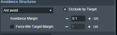 Fig. 53: Selected avoidance structure
- Force min target margin: disabled by default, when enabled it will force a minimum margin around the target taking priority over the settings of the avoidance structure.
For example: As shown below, there is an overlap between the margin set for the avoidance structure and our target structure. Since “force min target margin” is disabled, the avoidance margin has priority over the target.
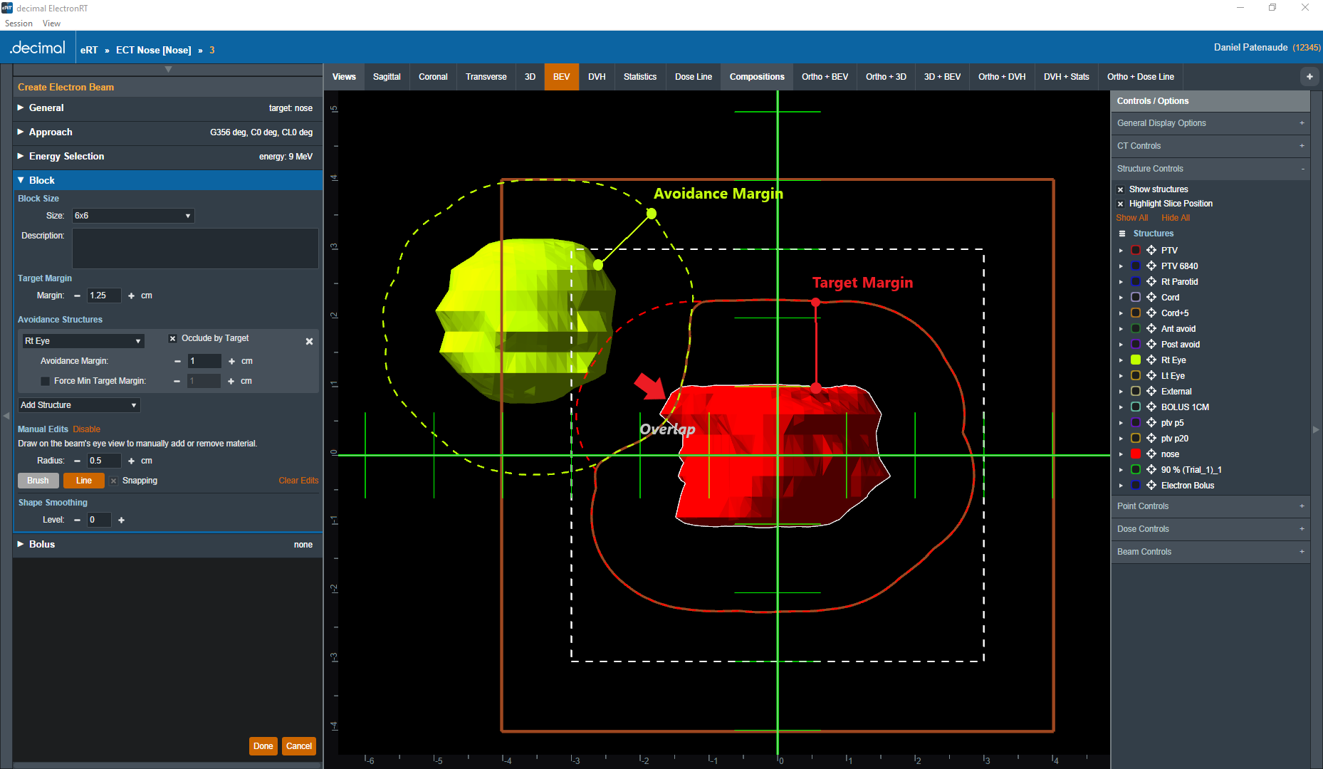 Fig. 54: Force min target margin is off
If the user decides that the target should have priority over the avoidance structure we can enable the “force min target margin” and set a min margin for our target. As you can see below the min margin set takes priority over our avoidance margin and there is no more overlap.
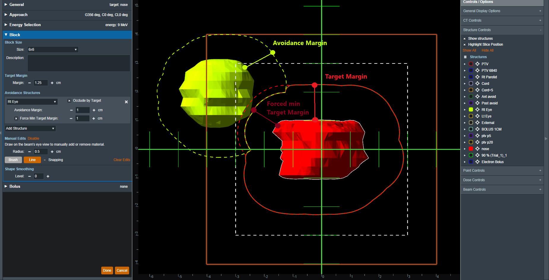 Fig. 55: Force min target margin is on
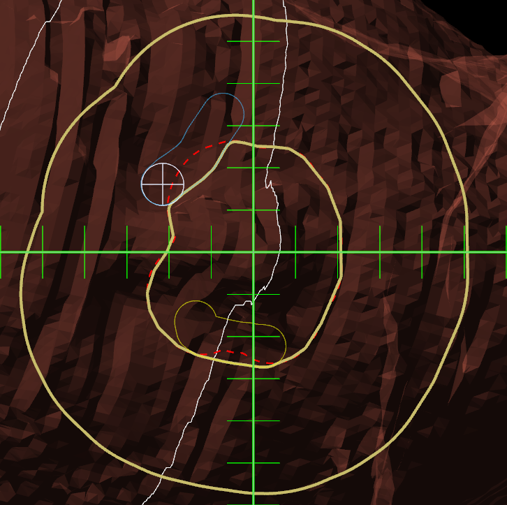
- Occlude by target: The user may also choose to occlude the structure by the target or not by using the “Occlude by Target” option. For the following examples we will use the Spinal Cord as it shows a dramatic example of differences of using or not using the “Occlude by Target” option. A 5mm margin was applied to the Cord for the following examples.
- Checking the “Occlude by Target” option makes the calculations account for the relative depth positions of the target and avoidance structure when determining the area to avoid. More specifically, the visible portion of the target (target volume that is in front of the avoidance structure) will not be blocked by the aperture. Note that just the inferior edge of the Cord is blocked by the aperture as this is the only portion that is visible (not behind the target) and the part of the Cord that is behind the PTV is not blocked.
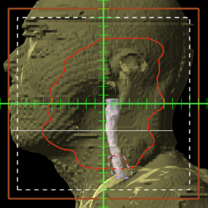
- Unchecking the “Occlude by Target” option makes the calculations ignore the depth order. This means the entire avoidance structure will be blocked, regardless of whether it is behind or in front of the target. In this example, the aperture now blocks out all of the Cord.


Manual Edits
By default manual editing of the block shape it disabled, but a user can elect to enable the ability to manually change the block shape.
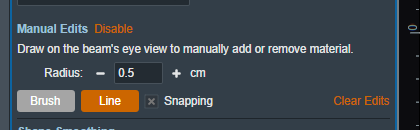 Fig. 56: Enabling manual edits
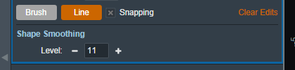
Once manual editing has been enabled you will see the cursor update to reflect the editing tool. You can choose to edit with the Brush cursor or by drawing straight lines using the Line tool. Both take in the radius that can also be set by the user to alter the size of the editing tool.
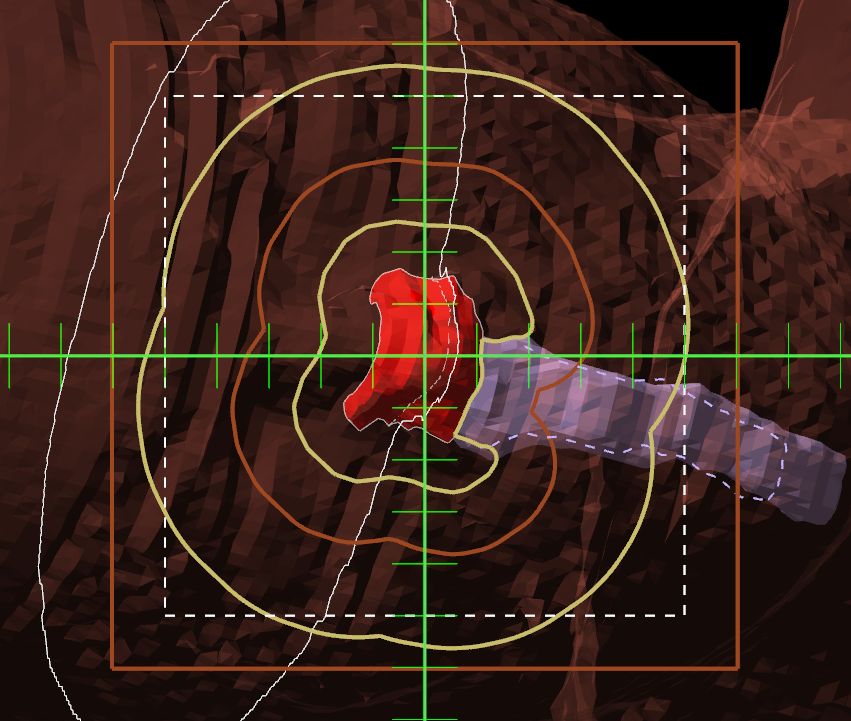
Note: Drawing on the “Exterior” of the aperture shape will shrink the shape of the block as can be seen below.
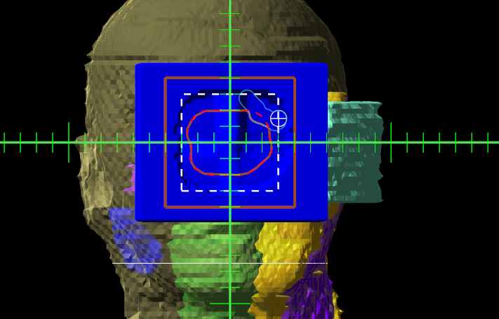 Fig. 57: Shrinking the block shape
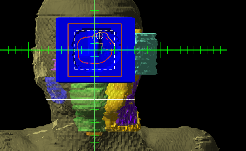
Note: Drawing from the “Interior” of the aperture shape will expand the shape of the block as can be seen below.
Shape Smoothing
Electron Bolus Creation
An electron bolus is an optional device for each electron treatment beam. A user is able to add an electron bolus to their beams to help improve the dose conformality to the distal target surface. The four options for bolus types in the decimal eRT app are fully defined below.
Optimized Thickness Bolus
The first option a user has for creating a bolus for the selected beam is an optimized thickness bolus. The goal for an optimized bolus is to best fit the specified Planning Isodose level of the computed beam dose to the distal surface of the target structure. The application provides reasonable default parameters for designing such a bolus, so that in most cases, the user can simply click the “Generate Bolus” button and the application will design a suitable bolus automatically. Once the application has finished calculating, the bolus will get added to the beam.
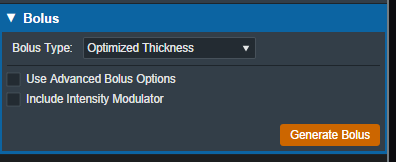
For complex and challenging plans, a user can also access advanced options to modify an existing bolus or create a new one from scratch.
In the advanced options you can view and manage various operators to augment the design of the bolus. The following operators are available:
Construction Operators (only available when first creating a new bolus):
- Automated Marching
- This operator constructs the proximal bolus surface using a series of incremental steps. Each step consists of a small thickness reduction at the optimally selected locations, followed by a hot spot damping step, in which the slopes of the bolus surface are reduced in areas where high dose values are found.
- Geometric Sequence
- This selection performs the following sequence of operators: Create, Smooth, Truncate.
- Single shift Sequence
- This selection performs the following sequence of operators: Create, Smooth, Isodose Shift, Smooth, Truncate.
- Double Shift Sequence
- This selection performs the following sequence of operators: Create, Smooth, Isodose Shift, Smooth, Isodose Shift, Smooth, Truncate.
- Create
- This operator constructs the proximal bolus surface by computing the difference between the physical depth to the distal PTV surface and the depth of the Planning Isodose level along each ray line of the bolus construction grid (for ray lines not intersecting the PTV, an extension is performed using the heights of the points that do intersect, which helps ensure the PTV edges are adequately covered).
Modification Operators (only available after a construction operator has been performed):
- Smooth
- This operator performs a Gaussian type smoothing on the current bolus proximal surface, which uses a distance weighted average of the neighboring point heights to compute a new height for each bolus surface point.
- Isodose shift
- This operator updates the bolus proximal surface by using the dose results with the current bolus in place to adjust the bolus heights by the difference between the position of the Planning Isodose contour and the position of the distal PTV surface.
- Truncate
- This operator updates a bolus proximal surface by reducing the height of the bolus in the region outside the Block Outer Border. The height is reduced to be slightly above the highest point in the modulated region. It should be mentioned that truncating a bolus may limit the ability to shift points upward (increase in thickness) when performing manual isodose shift operators after the truncate.
- Specified Shift
- This operator updates a bolus proximal surface by shifting all points (even the region beyond the Block Outer Border) by the specified distance.
- Intensity Modulation
- This operator manually adds an Intensity Modulator device to the beam. If multiple Intensity Modulation operators are added in the operator list, then the results of the multiple iterations of the modulation calculation are combined to produce a single Intensity Modulator device for the beam.
If an operator is selected from the list the UI will update to show the options for that operation. Once the options have been finalized the user can add the operator to the list which will re-compute the bolus and IM devices for the beam.
Below is an example of adding the automated marching to a new bolus:
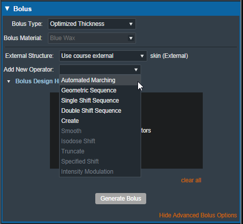 Fig. 62: New bolus operator options
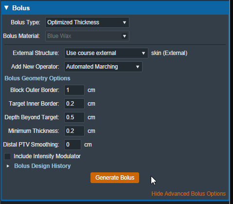 Fig. 63: Adding an automated marching operator
The advanced optimized thickness bolus design parameters allow the user to fine tune the bolus design for specific operators. These options include:
- Block Outer Border:
- The distance to extend the bolus surface beyond the block/collimator perpendicular to the CAX.
- Target Inner Border:
- Specifies the distance to offset the target projection inward when defining the region over which initial construction and smoothing operators act. This is used to reduce the effects that the rapid PTV height changes near the target edges can have on the construction and smoothing operators.
- Depth Beyond Target:
- The beams-eye-view distance past the selected target (along the CAX direction) at which the patient-side surface will be truncated.
- Minimum Thickness:
- The minimum allowable thickness of the bolus as measured along a beam aligned rayline.
- Distal PTV Smoothing:
- The smoothing ball radius used to smooth the target structure. A larger radius will result in more smoothing but will also cause a greater deviation of the target from the original structure. Note that setting this value to 0 mm will result in no smoothing for the target structure.
- Smoothing Weight: (Smoothing operator only)
- The exponential smoothing weight coefficient (smaller value increases smoothing)
- Smoothing Size: (Smoothing operator only)
- The smoothing distance factor (larger values spread the smoothing range further)
- Additional Thickness: (Specified Shift operator only)
- The thickness to add to the bolus proximal surface (use a negative value to reduce height)
Additionally by selecting the “Bolus Design History” you can see a list of every step in the bolus design. The last step is removable individually, and there is also the option to clear all steps and start from scratch.
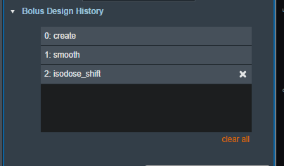 Fig. 64: Bolus design history list
When designing an optimized thickness bolus, you also have the option to select the patient external structure. By default, this is set to the external structure defined in the course.
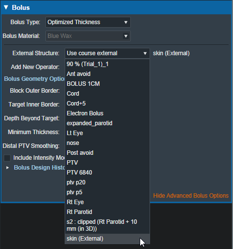 Fig. 65: Bolus external structure selection
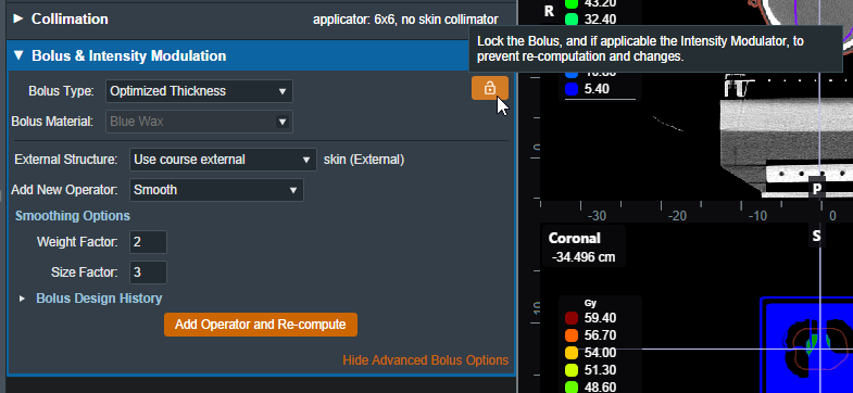
If you want to make changes to the beam without having the optimized thickness bolus re-calculate, there is a lock button that prevents the optimized bolus from changing during other beam changes (e.g.: changing the block shape will normally cause the bolus to re-compute). This will lock the bolus design and prevent any changes. If anything in the beam is changed after locking the bolus and the bolus is unlocked then the bolus will be re-computed using the new beam parameters.
Uniform Thickness Bolus
Uniform Thickness Bolus devices are designed at the plan level, but they must be added to each intended beam individually to ensure the computed dose accounts for the presence of the bolus in the beam path.
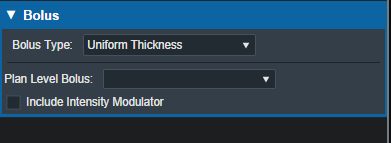
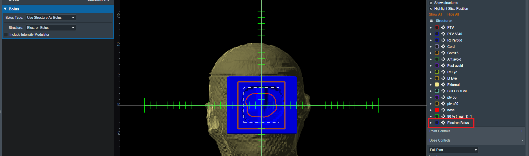
Structure as Bolus
The user also has the option to use existing plan structure as a bolus. Once this option is selected, the user will be able to choose the structure from the drop down list and the app will set it as a bolus for this beam.
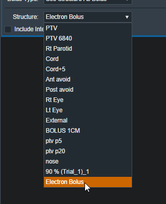 Fig. 68: selecting from the structure list
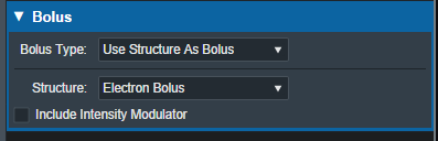 Fig. 69: selecting a Bolus as a structure
Once the structure is selected the bolus will be added to this beam and dose re-calculated.
Note: The bolus is displayed in the BEV for this beam even though the “Electron Bolus” structure is hidden through the right hand side controls. This shows that the displayed bolus is added as a bolus on this beam and not appearing as a structure.
If you wish to import a bolus that is not currently in your structure list please refer to the DICOM Patient Import section of the user guide for how to re-import a structure set.
Intensity Modulator Device
Additionally if any type of bolus is added to a beam the user is able to also include an Intensity Modulator by selecting the option below any bolus type. The user will then have the option of modifying the dose scaling value applied when calculating the positions and diameters of the intensity modulation pins. The application with calculate the device and display it in the beams UI.
NOTE: In order to add an IMET device the selected beam MUST have a valid bolus.
Circular applicator shapes (e.g.: Siemens 4×4) are not supported for intensity modulators.
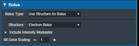 Fig. 71: IM Dose Scaling control
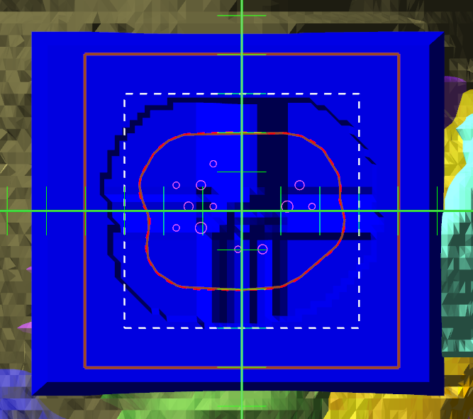 Fig. 71: BEV IMET
As with a bolus, the IM device can be hidden and un-hidden from the display using the beam controls on the right hand size.
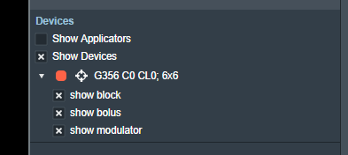 Fig. 73: RHS options to hide/show devices
Users with Elevated Physics level permissions are able to import a user-defined intensity modulation device. The imported device file must be a .csv file with the format: X,Y,Diameter for each pin on a new line. The values must be at the physical block/tray position and the pin diameters must match the supported modulator diameter list.
An example file is:
- im_file_example.csv
0.3,-1.55885,0.352
-0.3,1.55885,0.158
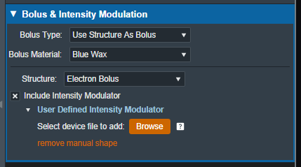 Fig. 74: Option to import user defined intensity modulator file
Skin Collimator Creation
A skin collimator is an optional device for each electron treatment beam. In the Collimation block, the user can create and edit skin collimators for the selected beam as well as edit values for an existing collimator. From within the Electron Beam Task you may add a skin collimator to a beam by clicking the “Use Skin Collimation” checkbox from within the Collimation Block.
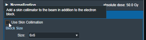 Fig. 75: Skin Collimation Checkbox
A note regarding the use of skin collimation with bolus
Skin collimation can be added to any beam and used with any bolus type, however, only an Optimized Thickness Bolus will automatically conform its shape to correctly account for the presence of a skin collimator. Therefore, caution must be used with all other bolus types as the user must manually review the bolus and skin collimator to ensure there is an appropriate fit (e.g. no overlap, interference, or unwanted air gaps) between the skin collimator, bolus, and patient surface.
Collimator Thickness
- Thickness: The value (in cm) of the thickness of the skin collimator from the surface of the patient external structure.
Note: The default Thickness value is automatically calculated based on the beam energy. To edit the thickness, click the “edit” control to the right of the thickness value. The app will automatically recalculate and display changes to the skin collimator as the thickness is edited.
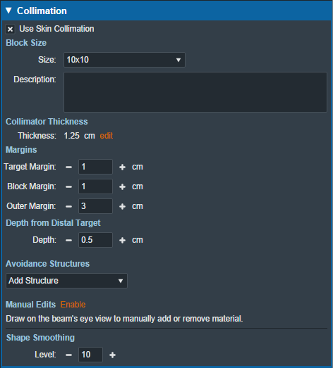
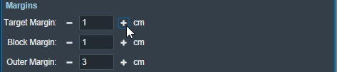
Margins
- Target Margin: The value (in cm) of the margin around the target structure as projected to isocenter. A negative margin can be used to specify a contraction around the beam target while positive values will cause an expansion.
- Block Margin: The value (in cm) of the margin between the skin collimator opening shape and the electron block opening shape. When a skin collimator is added to the beam, the block opening shape becomes an expansion of the skin collimator opening shape according to the block margin value. Any edits made to the shape of the block opening will be transferred to the skin collimator opening shape when the users chooses to add skin collimation to the beam.
- Outer Margin: The value (in cm) of the margin between the skin collimator opening shape and the outer shape of the collimator as projected to isocenter. A negative margin can be used to specify a contraction of the outer skin collimator shape while positive values will cause an expansion.
Note: The app will automatically recalculate and display changes to the skin collimator as the margins are edited.
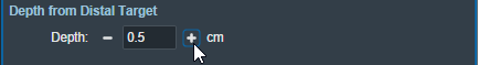
Depth from Distal Target
- Depth: The value (in cm) of the depth from the distal side of the beam target that is used when calculating the skin collimator 3D shape. Adjusting this value can help improve the skin collimator shape in some situations.
Note: The app will automatically recalculate and display changes to the skin collimator as the depth from distal target is edited.
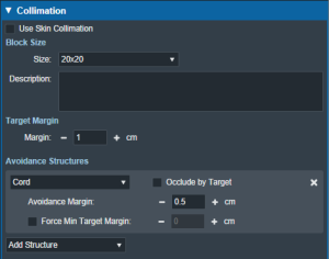
Collimator Avoidance Structures
Using controls that are shared with electron blocks, the user may select one or more structures in the structure list here to add as an Avoidance Structure. Avoidance structures will decrease the skin collimator opening to remove all areas within the projection of the structure. Note that avoidance structures will also affect the shape of the electron block opening as it is an expansion of the skin collimator opening.
Collimator Manual Edits
By default manual editing of the block shape it disabled, but a user can elect to enable the ability to manually change the skin collimator opening shape in a manner that is identical to Manually Editing the electron block opening shape. Note that manual edits will also affect the shape of the electron block opening as it is an expansion of the skin collimator opening.
Collimator Shape Smoothing
- Level: Sets the level of smoothing applied to the skin collimator opening shape. This does not smooth the patient or beam side surface of the skin collimator.
Note: The app will automatically recalculate and display changes to the skin collimator based on the set smoothing level.
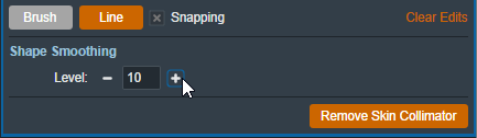 Fig. 81: Setting the smoothing level for the skin collimator
Plan Approval
Plan Approval is a mechanism whereby users can “lock” a plan to prevent further edits or changes once it has been reviewed by a qualified radiation therapy professional (typically a licensed Radiation Oncologist). It should also be noted that before users are able to order blocks or boluses in the ElectronRT app, the plan for those parts must be approved by a user with the 'Plan Approval' permission. This action ensures parts are not ordered for plans that have not been properly reviewed.
Approved plans differ from unapproved plans in the following ways:
- They are read only and no treatment plan data can be changed
- The plan dose and hardware devices are no longer being recomputed in the UI as during approval those items are saved to the patient disk storage to ensure they never change from how they were viewed at the time of approval.
- The Ordering and Plan QA blocks are enabled
Note, Plans can not be unapproved.
 Fig. 82: Plan selection with no approvals
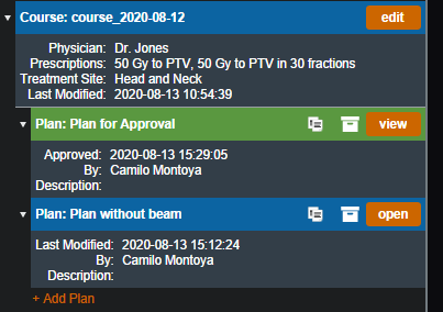
When a user goes to select a plan for a course for their patient, they will be able to tell if the plan is approved or not. Plans that are green are approved while unapproved plans are the standard blue. Approved plans also state the time they were approved and by which user in order to maintain integrity with the plan.
Approving a plan
In order to approve a plan a user must simply open the plan they wish to approve and select the “Approve” option inside the General Block.
NOTE: The option will not appear in the following situations:
- The user does not have permission to approve plans
- The plan has no valid beams or there are un-handled errors with the existing beams
- The plan does not have valid dose
In any of these cases the general block will look as such:
 Fig. 84: Approval option hidden
After logging in with an appropriate user and opening a plan that is ready for approval you should see the option available in the general block.
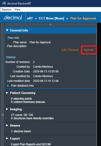 Fig. 85: Approval option available
After selecting to approve a plan a user must confirm their selection. They will also have a final opportunity to change the Name and/or Description for the final plan.
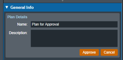 Fig. 86: Import Directory Input
When that is completed all users on this environment should see the plan as approved (see Figure 2).
Plan Reports
The ElectronRT App allows PDF export of treatment plan reports. Treatment plan reports include all patient, plan, and beam data and can optionally include screen shots taken in the application.
Note: The Export block will be disabled if no machine or CT curve exists in the site configuration.
Report Customization
The ElectronRT App provides options for customizing the exported plan report including: customizing the header logo and setting the different options for details that will appear in the report.
Header Logo
By default, the header logo is set to the logo of the application. The header logo can be optionally overridden by the user in the Organization Configuration block. For more information please refer to the Organization Settings.
The header will be placed as shown in figure 88. The header image is not scaled and is placed on the report at its native size.
Recommended Size
Since the custom header image is not scaled when placed into the report, it's recommended to use a size that does not interfere with the report contents or reduce the readability of the report.
As such, the recommended image size for a custom header logo is:
- Width: 200 to 500 pixels
- Height: 40 to 75 pixels
Larger sized images may still render correctly on the report as long as they fit a standard portrait letter size, but are not recommended since they may impact readability of the report. Images larger than the PDF page may have the image cropped to fit on a single page.
Screen Shots
Users are able to take screen shots to include on their treatment plan report. Screen shots will include the entire display UI including all CT, Dose, 3D, BEV, and statistics views. Once a screen shot has been captured it will appear on the exported treatment plan report
After specifying a name for the screenshot, the application will allow the user to capture the current display and save the screen shot for the plan report.
Managing Screen Shots
Once a screenshot has been captured the following actions can be performed for each screen shot:
- Preview/View: You can view the captured screen shot by selecting the screenshot in the list of saved captures
- Delete: You can remove a captured screenshot so that it is no longer exported to the treatment plan report by selecting the 'X' icon next to the screenshot name.
Report Content
By default, plan reports will contain all plan information currently present in the treatment plan. Users can optionally choose to not export specific content to the treatment plan report including: dose reference points, density overrides, beams, or ordered hardware information.
Coordinate System (Equipment & IEC)
By default, the treatment plan report will export beam geometry information in the equipment coordinate system. Users can optionally choose to export beam coordinates using the IEC coordinate system as specified in the Machine Configuration. This option is provided as a checkbox in the Report Content Options section.
The selected coordinate system option will be displayed on the treatment plan report as either “Equipment” or “IEC” as shown in the figure 90 below.
 Fig. 90: Report Coordinate System
For more information on setting the IEC coordinate systems please refer to the Machine Geometry Settings.
DICOM Export
The ElectronRT App allows for the export of patient and plan information in the DICOM file format. If the treatment plan is not approved, authorization from a qualified user is required to enable export.
Note: The Export block will be disabled if no machine or CT curve exists in the site configuration.
The user can choose to export the CT Images, RT Structure Set, RT Plan, and RT Dose as DICOM files. There are a few considerations to keep in mind for each DICOM file that is exported from decimal eRT:
- CT Images:
- The ElectronRT App allows CT Image export for the convenience of end users only. This application does not modify CT Images in any way and the exported CT Image files are exact copies of those imported into the app for the patient course at hand.
- Structure Set:
- Exported RT Structure Sets will be an exact copy of the imported Structure Set data, with a few notable exceptions:
- The exported RT Structure Set will include override material information for any structures to which the user has applied density overrides in the treatment plan.
- Structure(s) will be added to the Structure Set for any bolus that are present in beams within the treatment plan.
- If the user changes the External structure in the Course, that structure will be marked as the External in the exported RT Structure Set.
- RT Dose:
- The computed dose can be exported as a single Plan level RT Dose file as well as separate RT Dose files for each treatment Beam.
For unapproved plans, new UIDs will be generated each time the plan is changed and DICOM files are exported. For approved plans, the DICOM UIDs are fixed and will always be the same each time the DICOM file is exported.
Local Export
The ElectronRT App allows the export of DICOM files to a local directory. A default DICOM export directory can be set in the Site Configuration DICOM Settings.
Server Export
The app also allows the export of DICOM files to a DICOM server (AE title). When exporting to a DICOM server, the user can choose to export to a server defined in the Site Configuration DICOM Settings or to a custom server.
Ordering Devices
Once a plan has been approved, the user is able to order the devices that were added to the beams in the plan. Ordered devices will be sent to .decimal for manufacturing through decimal Direct via secure HTTPS.
Note:
Skin Collimator ordering is currently not supported.
 Fig. 92: Part Ordering Example
Select the “order devices” option and all devices will be shown to the user along with the beam in the plan that utilizes said Device. From here users can select which devices they would like to order and move on to the next step.
 Fig. 93: Part Selection Example
Once the user has decided which devices to order, the following fields will need to be filled out in order to complete the order.
- Shipping Address: The address the devices will be shipped to. The areas listed here can be edited or new ones added from the Organization Configuration block.
 Fig. 94: Ordering Info Example
- Shipping Priority: Standard (Overnight delivery by end of day) or Rush (Overnight delivery before noon).
- Note: Extra charges may apply for Rush delivery.
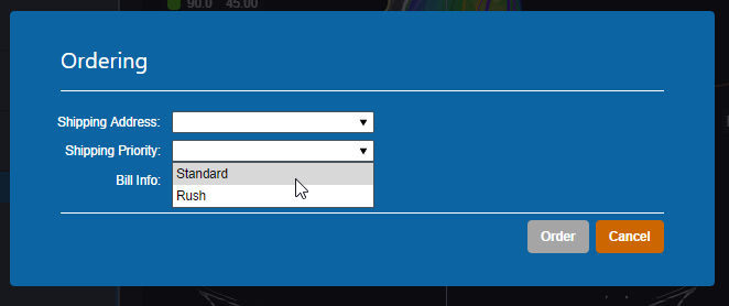 Fig. 95: Shipping Priority Selection
- Bill Info: Any additional PO or specific Billing information to be added to the order. This is an optional field.
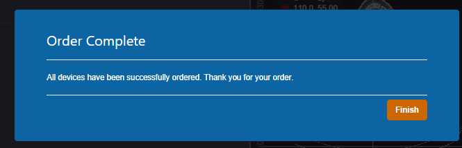
Once these fields have been filled the device(s) can be ordered and the user will be provided with a confirmation if the order is completed successfully.
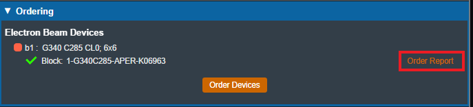
After the order has been placed to decimal Direct the ordered devices will be noted within the Ordering block. Additionally users can view the order report for that device by selecting the highlighted link. This will take the user to the decimal Direct page with the order confirmation for that device.
Plan QA
The ElectronRT App includes a set of QA Tools that allow the user to measure each treatment beam dose on a water phantom, compute dose on bolus simulation CT images and compare results, and export QA PDF reports. The QA Tools block is only enabled for approved treatment plans.
Dose QA
The Dose QA block computes and displays the dose for each beam in the treatment plan to a water phantom. For each beam, the user is able to define the SSD and the depth of a measurement plane. This measurement plane will be used to take a cross-sectional sample of the water phantom dose. If a custom water phantom was added to the Site QA Options, the Dose QA block will default to the custom phantom and the user will be able to choose between that and the default phantom. The dimensions of the default water phantom, as well as the default measurement plane depth and dose grid spacing, are defined and editable in the Site QA Options.
After defining the measurement plane depth for at least one beam, the user will be able to click the Export QA Dose Files button to export a QA Dose DICOM file for every measurement plane dose to a local directory. The exported DICOM will include:
- A 1cm thick dose image around the set measurement plane
- [optional] The full 3D water phantom dose - if the user has selected the full 3D dose export option
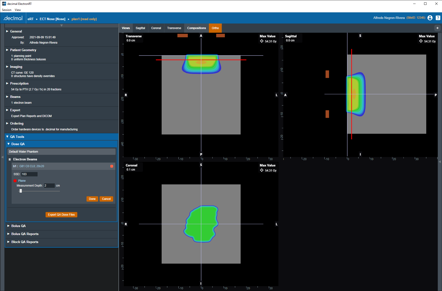 Fig. 98: Dose QA Default Water Phantom
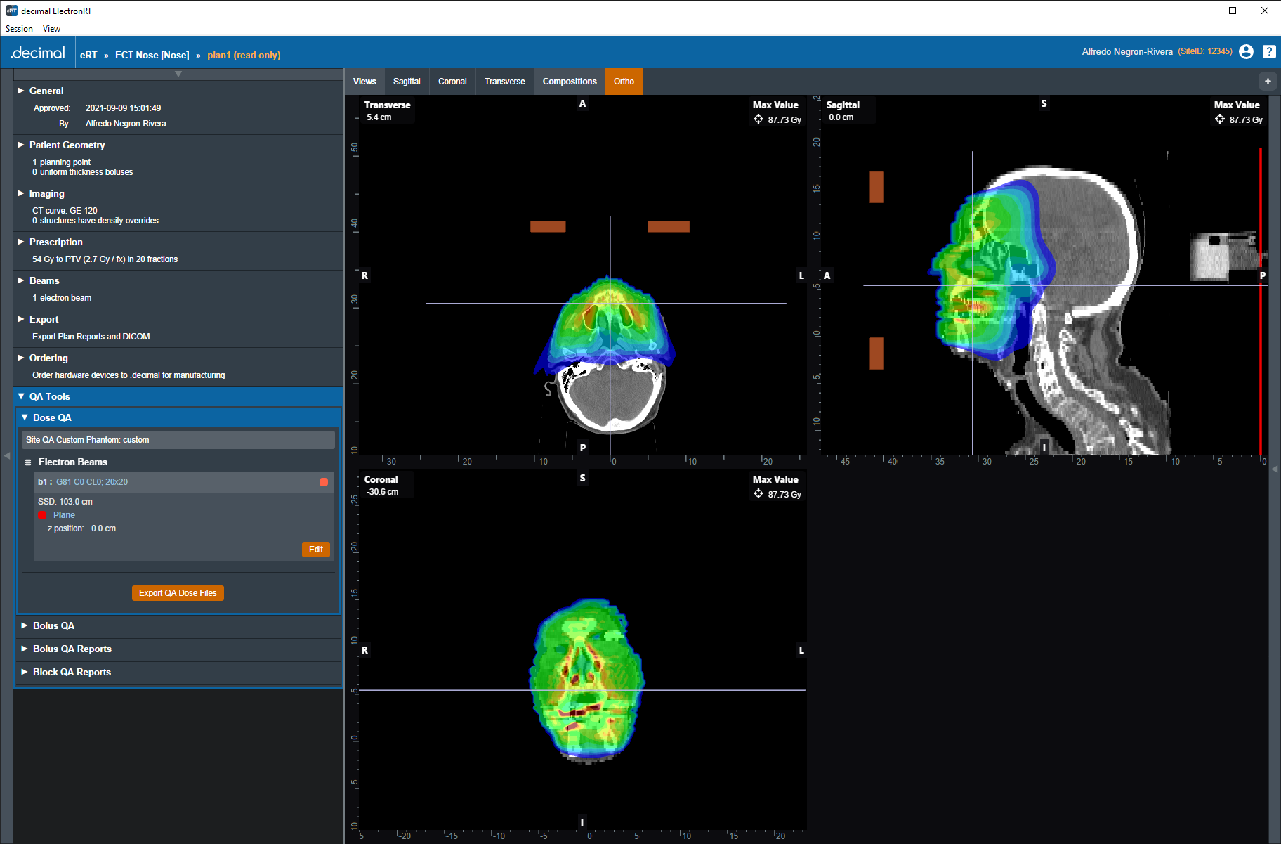 Fig. 99: Dose QA Custom Water Phantom
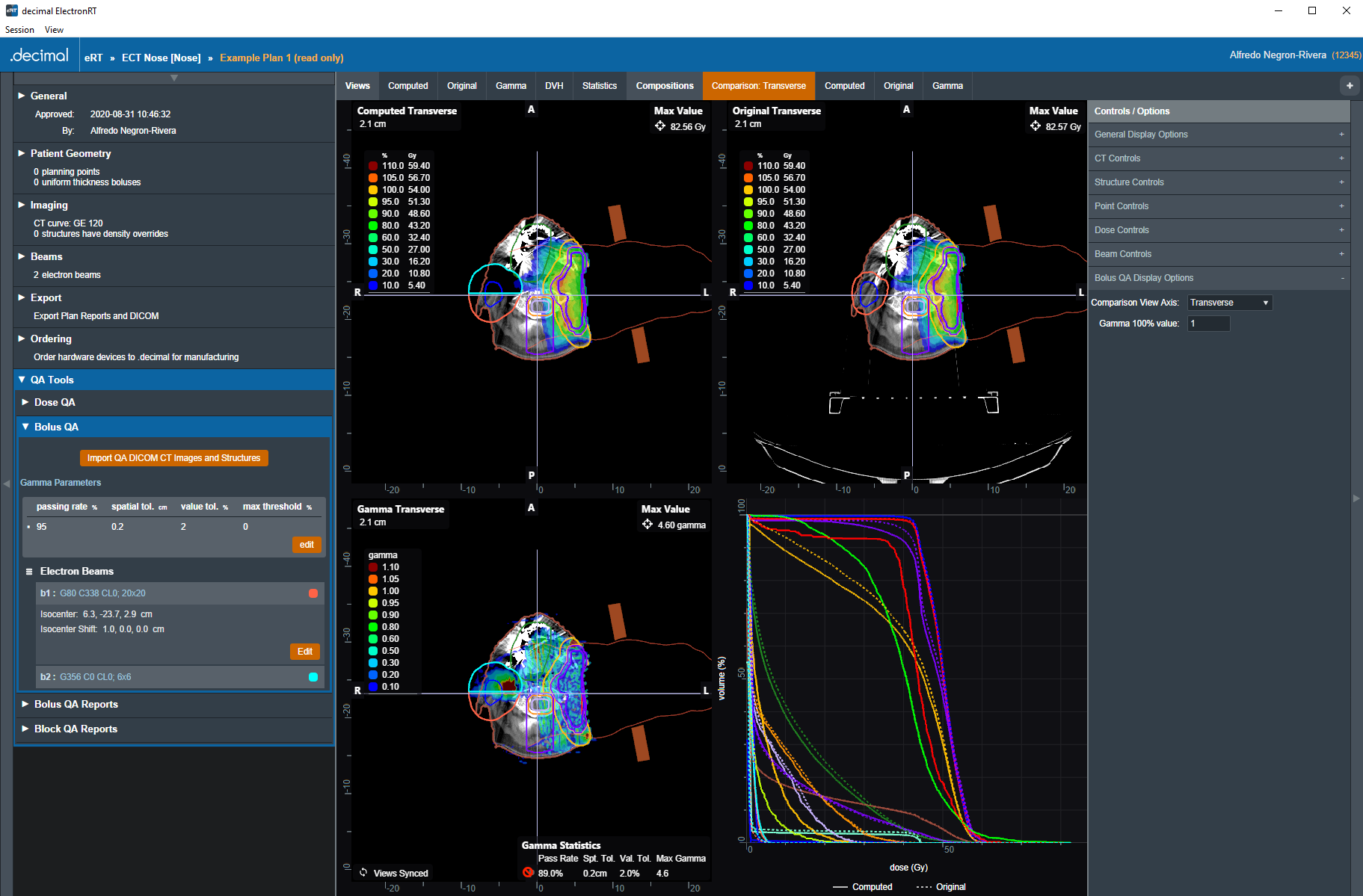
Bolus QA
The Bolus QA block allows the user to import DICOM CT images and an optional structure set used for bolus QA simulation. The process is very similar to the DICOM Patient Import.
QA is performed by computing dose on the re-imported CT images (which now contain the actual manufactured bolus) using the same beams as the original treatment plan. The recomputed dose, as well as the original plan dose and a comparison image (using gamma score), are available for display in the UI. The user can edit the Bolus QA block controls to change the gamma parameters as well as shift the isocenter for each beam in the re-computed dose to account for positional shifts in the bolus simulation CT images.
The comparison view shows the three images simultaneously on the corresponding CT images as well as a graph displaying the DVHs for the original and re-computed dose images. The user can switch between Transverse, Sagittal, and Coronal for the comparison view in the Bolus QA Display Options in the right side controls.
Users can also set the gamma calculation parameters and required passing rates. This includes:
- Passing Rate (%): The percentage of voxels that must be within tolerance in order for QA to “pass”.
- Spatial Tolerance (cm): The maximum allowable distance-to-agreement (DTA) value, where DTA is the distance from a point in the original dose field to the nearest point in the re-computed dose field the has the same dose value.
- Value Tolerance (%): The maximum allowable dose difference between corresponding points in the original and recomputed dose fields.
- Max Threshold (%): The relative dose value below which dose comparison calculations will no longer be performed
Bolus QA Reports
The Bolus QA Reports block allows the user to export PDF reports with data gathered from the Bolus QA block. Just like with Plan Reports, the user can add screenshots of the Bolus QA display UI to the Bolus QA report.
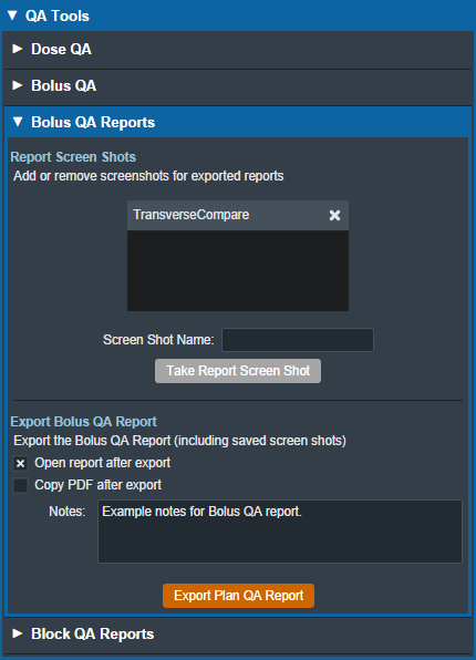
Bolus QA reports contain basic patient and treatment plan information as well as gamma analysis results, dose reference point data, and structure dose statistics.
Block QA Reports
The Block QA Reports block allows the user to export PDF printouts of the electron blocks used in the treatment plan. The user can choose to display each block as a physical (true size) or isocenter projection. There is also a printer-friendly option that removes the color from the block projection (note that for large fields these reports may span multiple pages).
Organization Configuration
The ElectronRT App allows for users with certain permissions to view and edit organization level configuration settings. The Organization Configuration block is located in the main page of the app and is only visible to users with Physics or higher level permissions.
Organization Settings
The Organization Settings block allows the user to view and edit settings that affect the entire organization. These settings include organization name, PDF report logo, CT override materials, and electron device materials.
 Fig. 107: Organization Settings
While editing the settings in the Organization Configuration block, the UI is changed such that the user cannot click on other sections of the UI until confirming edits with “Done” or canceling edits with “Cancel”. Some settings are grouped into tabs, such as the “General” and “Materials” tabs in the Organization Settings.
Materials
The Materials definitions allow specifying the device materials and CT override materials. These materials will be usable across the entire organization and all sites.
The units for the materials are as follows:
- density: g/cm3
Dose Colors
The Dose Colors definitions allow users to specify the default dose colors and levels when creating new plans. These values will apply to all plans created within the organization across all sites.
 Fig. 110: Dose Colors Configuration
Note: The dose color options set will only be applied to newly created plans. For existing plans select the 'reset to defaults' link within the Dose Controls right hand side user interface to revert to the site level defaults.
Organization Import/Export
The organization import and export user interface allows users to backup, copy, or give their organization data to other individuals as needed. The following details are worth noting about this feature:
- The organization data will not be readable as plain text.
- If applicable, when importing an organization file the organization data will be upgraded to the latest version of the data model and automatic upgrades added where appropriate. Refer to the release notes for previous versions of the organization since it was last exported for the values of these upgrades.
- The application will need to be restarted after successfully importing a new organization.
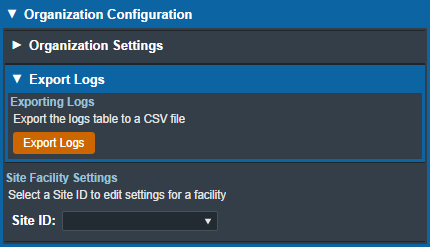
Export Logs
The Export Logs block allows the user to export a file containing logs of user activity within the app. This .csv file contains data exported from the app database that keeps track of critical user activity, including (but not limited to): opening of patients and plans, plan approvals, report/DICOM exports, and hardware ordering.
Refer to the decimal eRT User Logging guide for details on what actions are logged.
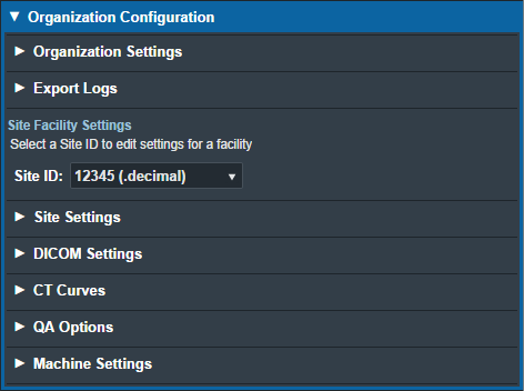
Site Facility Settings
The Site Facility Settings section of the Organization Configuration allows users to view and edit settings for each site in the organization. After selecting a Site ID, the site level settings are divided into five categories: Site Settings, DICOM Settings, CT Curves, QA Options, and Machine Settings.
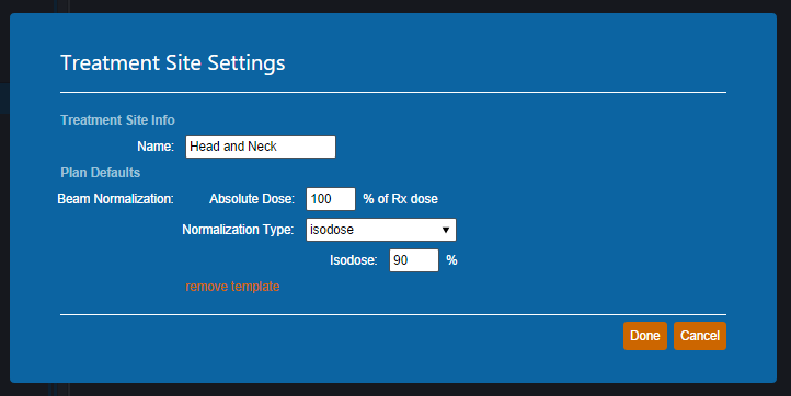
Site Settings
The Site Settings block allows for the viewing and editing of miscellaneous site level settings including the site address, physicians, and treatment sites. When editing the site address, the UI has an option to set the address to the one assigned to the site in decimal Direct. In order to edit physicians, the user must first click on the physician name on the list of physicians on left side UI and then click on “Edit Physician” on the right side UI (this is also the case with treatment sites). Users can add or remove physicians and treatment sites using the left side UI.
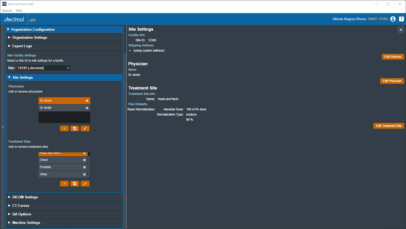
Plan Defaults / Templates
Beam Normalization
The user can assign a beam normalization template when editing a treatment site. This template will be used to set the normalization during automatic beam calculations for plans in the courses that are assigned to that treatment site.
Note: Refer to Electron Beam Normalization for using and the requirements of the beam normalization template within treatment plans.
DICOM Settings
The DICOM Settings block allows the user to view and edit settings related to the export & import of DICOM files. These settings include the default DICOM export directory, a list of DICOM export server AE titles, and the monitoring directory for DICOM Receiver imports.
These settings are applied and available to all users of the selected Site ID for which the settings are present.
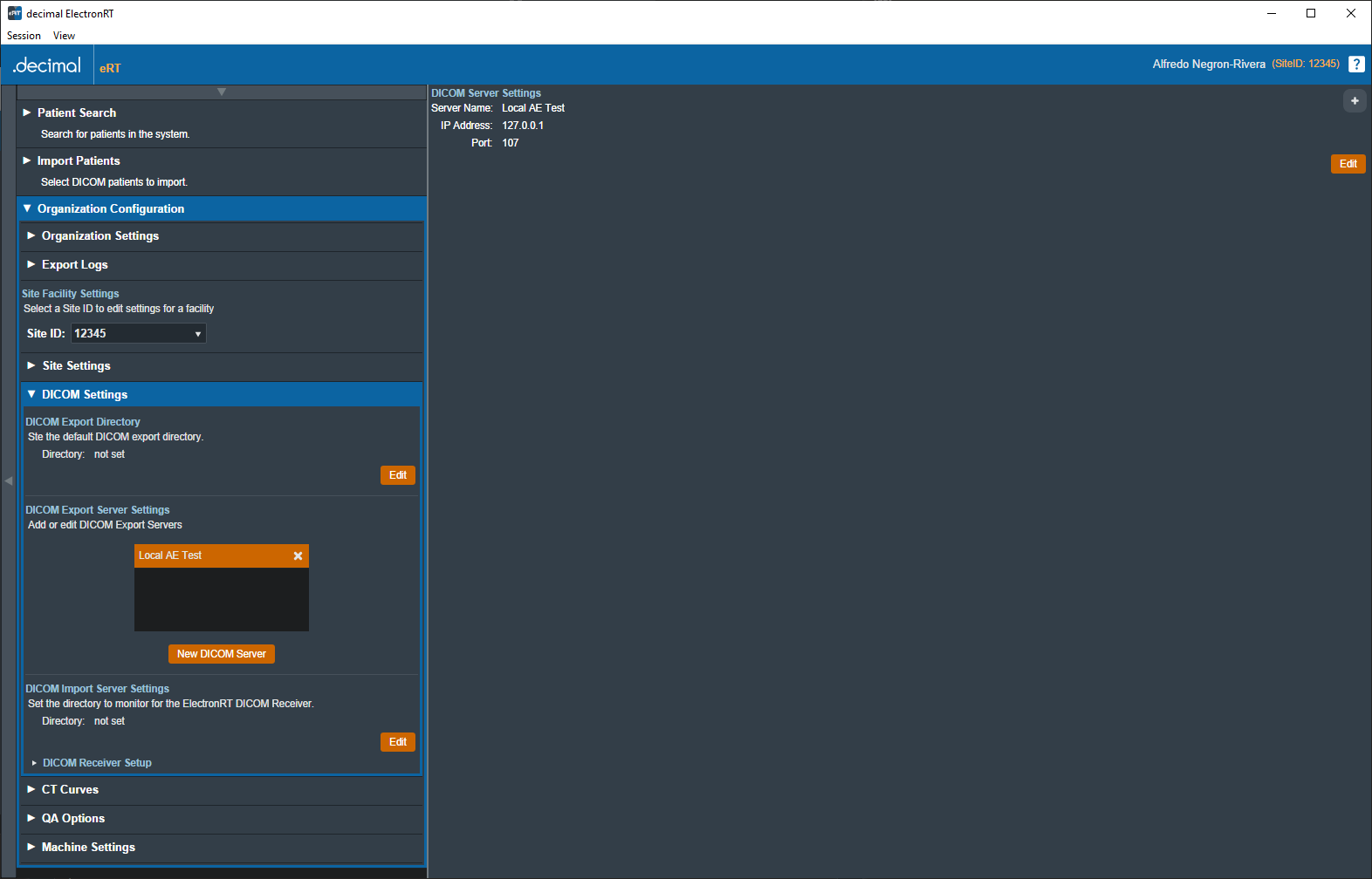
| DICOM Export Directory | ||
|---|---|---|
| Export Directory | Sets the default export folder when exporting DICOM files to disk. | |
| DICOM Export Server Settings | ||
| Export Export Servers | A list of DICOM AE titles (DICOM Receivers from another system) that the ElectronRT app can export to. | |
| Server Name: | The name of the DICOM server that will displayed to the user when exporting within the eRT app. | |
| IP Address: | The local network IP address to which DICOM files will be sent by the eRT DICOM sender. | |
| Port: | The local network port on which the DICOM sender should transmit the DICOM files. | |
| DICOM Import Server Settings | ||
| DICOM Import Monitoring Directory | Sets the monitoring directory for importing patients received from the ElectronRT DICOM Receiver. | |
CT Curves
The CT Curves block allows for the viewing and editing of CT conversion curves. These curves must contain data for both relative stopping and scattering power. The relative stopping power data for the selected curve is displayed on a graph on the right side UI. When adding a new CT conversion curve, the user can select and import a CSV file that fully defines the curve values. If there are no curves present, the user is able to obtain a sample CT curve file to have an example of the CSV formatting and values. Additionally, each CT conversion curve in the site can be exported as a CSV file.
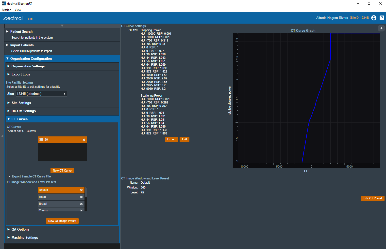
The CT Curves are defined as json as shown in the below example (note: this data is provided as a user guide reference only and should not be used in a commissioned treatment planning system; as such, it does not contain full values of CT curve data):
- CT Curve Example
{
   "scattering_power_curve": [
      {
         "key": -1000.0,
         "value": 0.0010
      },
      {
         "key": -706.0,
         "value": 0.2920
      },
      .
      .
      .
   ],
   "stopping_power_curve": [
      {
         "key": -10000.0,
         "value": 0.0010
      },
      {
         "key": -1000.0,
         "value": 0.0010
      },
      .
      .
      .
   ]
}
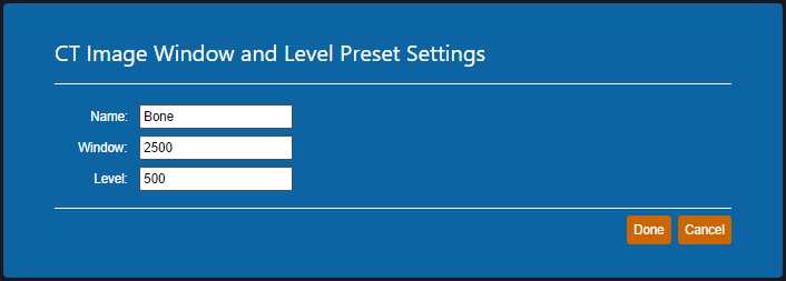
CT Image Window and Level Presets
The CT Curves block allows for the viewing and editing of CT image window and level value presets. These presets will appear as options in the right side CT Controls for electron plans in the selected site.
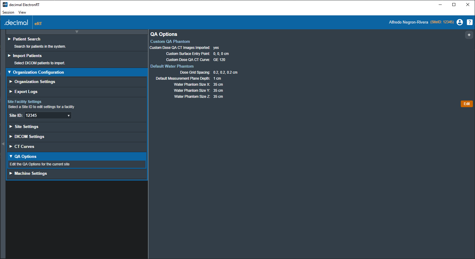
QA Options
The QA Options block allows the user to view and edit settings related to Dose QA. The UI allows the import of a CT image set that defines a custom water phantom. The user must define a surface entry point and select a CT curve when importing a custom phantom. Settings used for the default water phantom include the dimensions of the phantom, dose grid spacing, and the default measurement plane depth.
Machine Settings
The Machine Settings block allows the user to view, add, clone, and edit machines for the selected site. The machine settings are divided into five tabs: General, Geometry, Applicators, Commissioning, and Advanced.
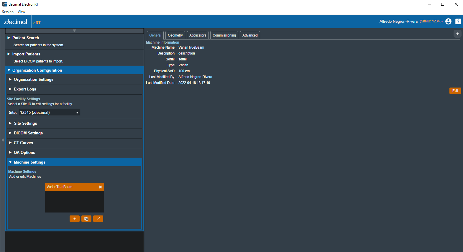
General Machine Settings
The General tab of the Machine Settings block allows for the viewing and/or editing of general machine information such as the machine name, description, serial, type, and physical SAD.
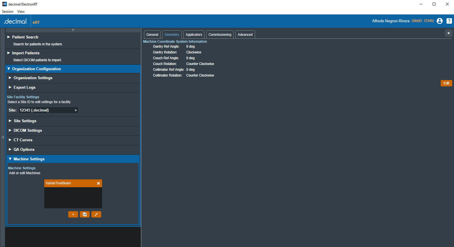
Machine Geometry Settings
The Geometry tab of the Machine Settings block allows the user to view and edit Machine (Equipment) coordinate system settings. These settings include the reference gantry angle, reference couch angle, reference collimator angle, and the rotation direction of each axis, relative to IEC 61217 coordinate system.
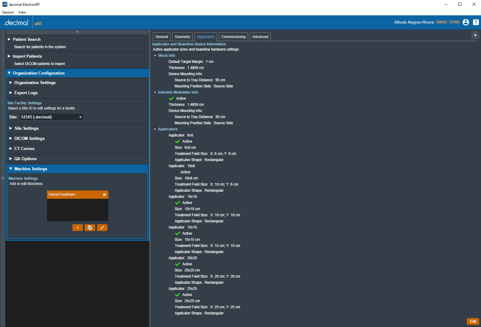
Applicator Settings
The Applicators tab of the Machine Settings blocks allows for the viewing and/or editing of applicator and beamline device settings. Information regarding blocks, intensity modulators, and applicators of varying sizes are displayed and the user can choose which applicators are available when creating a treatment plan using the current machine. The available applicators are dependent on type of machine (Siemens, Varian, or Elekta) chosen during the creation of a new machine.
While users are able to change the default target margin of the block, it should be noted that users are unable to change manufacturer specific settings (such as physical block size) as these have been pre-configured and validated by .decimal.
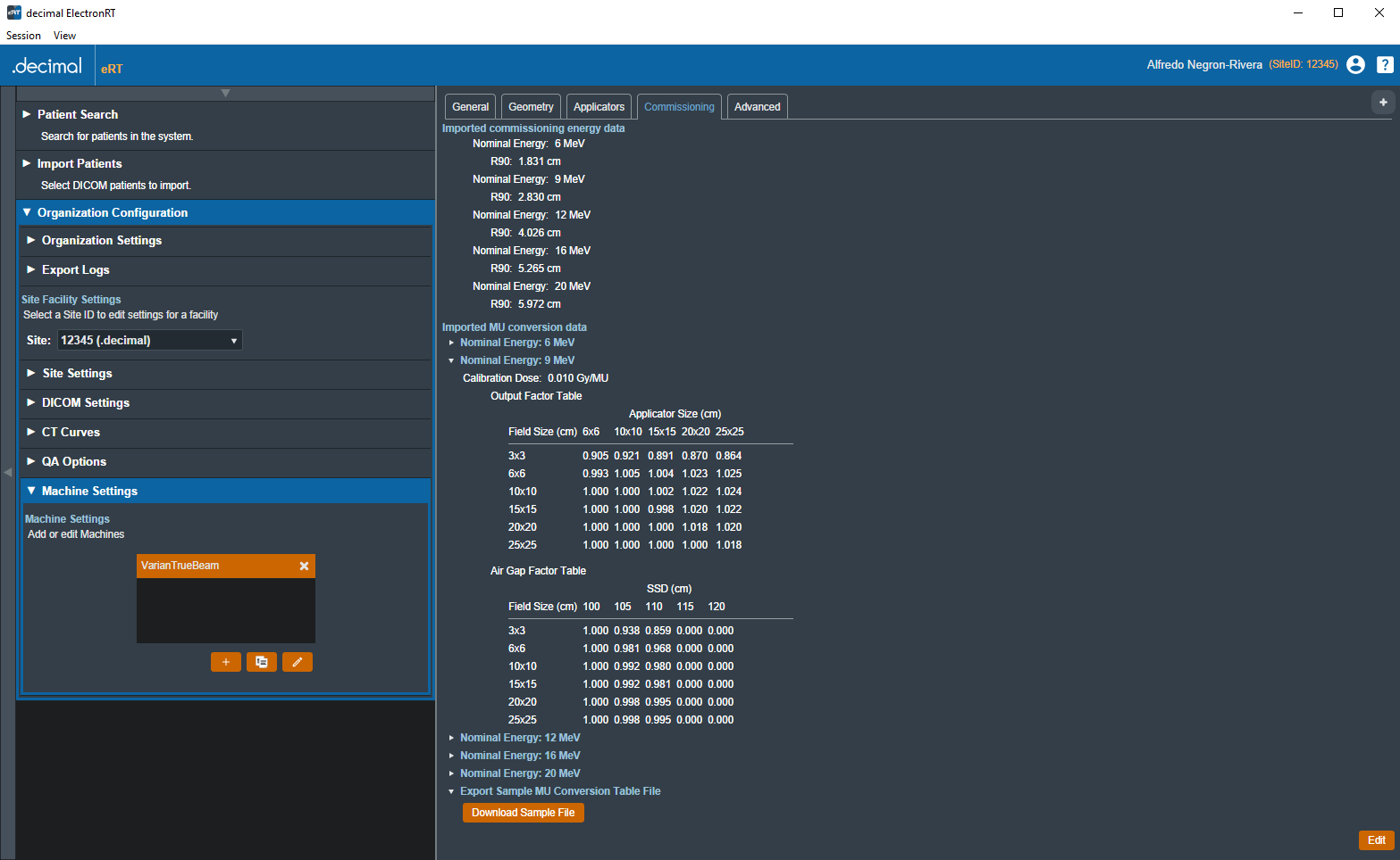
Commissioning Data Settings
The Commissioning tab of the Machine Settings block allows the user to view and edit commissioning data by energy. The user can view the nominal energy and R90 values of the current commissioning data or import new commissioning data from a local file. The ElectronRT App currently only has support for commissioning data import from the Pinnacle treatment planning system.
The Commissioning tab also allows the user to import MU dose conversion data tables and display them in the UI. Each MU data file must contain the Output Factor and Air Gap Factor value tables for a given beam energy. The user is able to obtain a sample MU conversion table file to have an example of the CSV formatting and values.
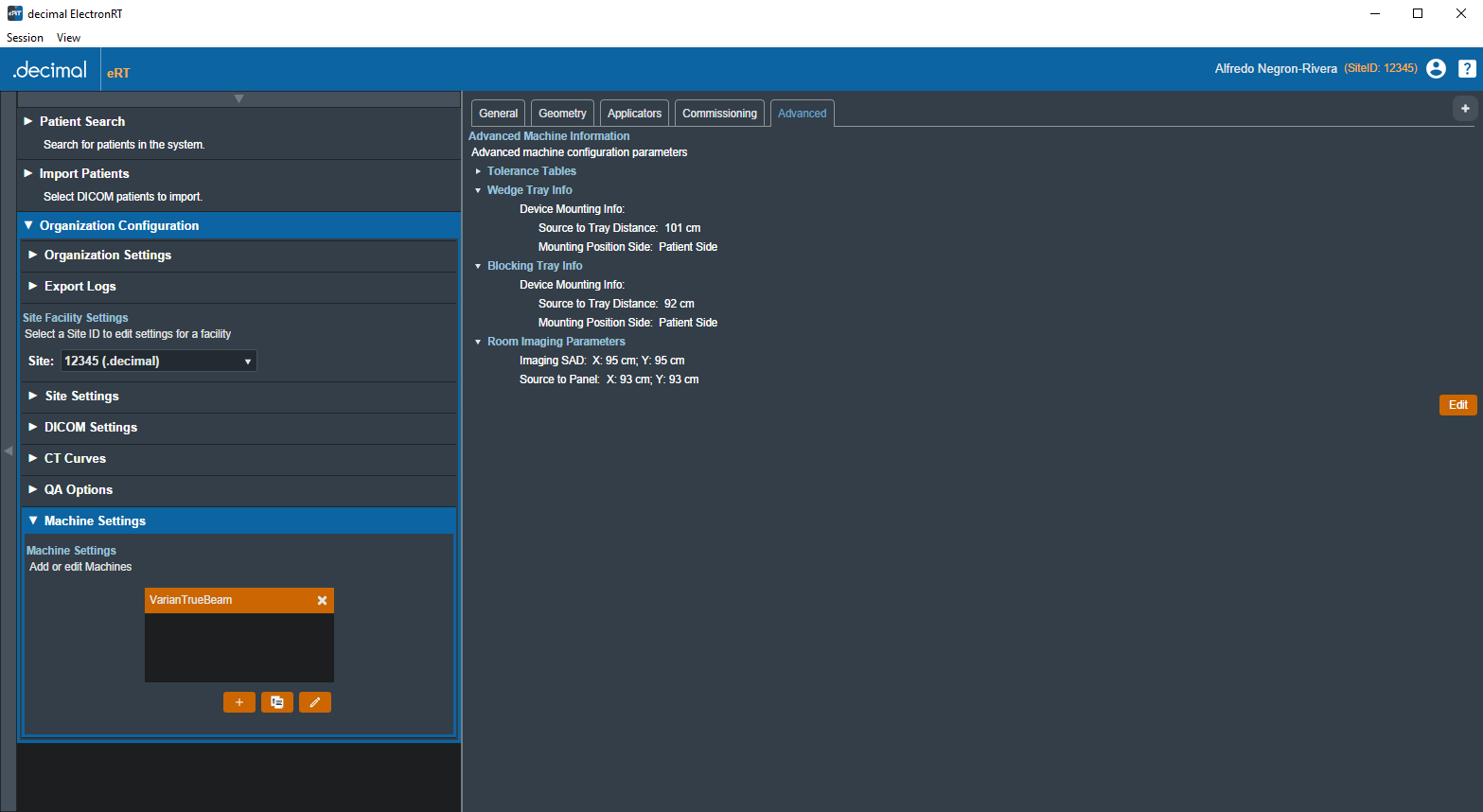
Advanced Settings
The Advanced tab of the Machine Settings block allows for the view and editing of advanced machine configuration parameters. These settings include tolerance tables, wedge tray information, blocking tray information, and room imaging parameters. These values are typically not used within the treatment planning process, but are included in DICOM Plan export to meet end user DICOM RT Plan requirements.
Sandbox Testing
decimal eRT provides a Sandbox isolated testing environment for evaluation of new application versions on non-clinical patient data. This testing mode is recommended to evaluate new release versions of the application prior to distribution to a site and it's users. The physics team at each site should evaluate all new application versions in the Sandbox environment to determine clinical acceptability of the new version following the all industry regulations and professional guidelines as well as the decimal eRT Instructions for Use (including but not limited to: comparison of plan dose, device design, QA, etc). Once the application version is deemed clinically acceptable by testing it in the Sandbox environment, the version can then be deployed for use by clinical staff.
Clinical data can be optionally copied into the Sandbox environment (see the Configuring Clinical Data for Sandbox section) or users can choose to start the Sandbox environment with no preexisting data.
The patient data storage and database for the Sandbox environment is completely isolated from the Clinical data. Any changes made within the decimal eRT application while in Sandbox mode will not transfer to the Clinical patient data (and vise versa, updates to Clinical data will not impact Sandbox data).
When in Sandbox mode, users will have full access to all application options as they are available to the user in the Clinical mode.
Note:
The Sandbox feature is accessible only for users with Elevated Physics access or higher.
Configuring Clinical Data for Sandbox
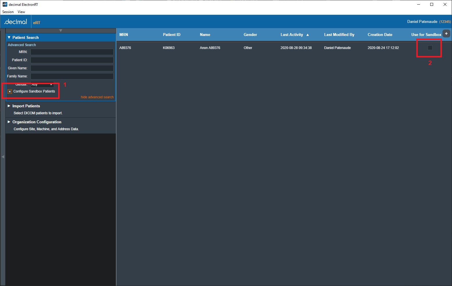
Users have the option to set Clinical patients for use in the Sandbox testing environment. When in the Clinical app privileged users can toggle on the advanced Patient Search option to Configure Sandbox Patients (shown in figure 124 at #1). When this option is toggled on each patient in the filtered display can be set to Use for Sandbox (shown in figure 124 at #2). Patients with this option set will automatically be imported into new Sandbox environments.
If no patients have been configured for use with the Sandbox environment an empty Sandbox environment will be created with only the site configuration.
Installing the Sandbox Version
Refer to the decimal Launcher Sandbox User Guide for installing an app version to the Sandbox environment.
Running Sandbox Testing
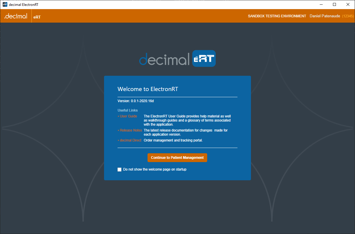
When the decimal eRT application is opened in Sandbox mode the application heading will be Orange and contain a warning that the user is in the Sandbox Testing Environment. This is to ensure there is no confusion to the user about which environment the application is in.
First Time Sandbox Use
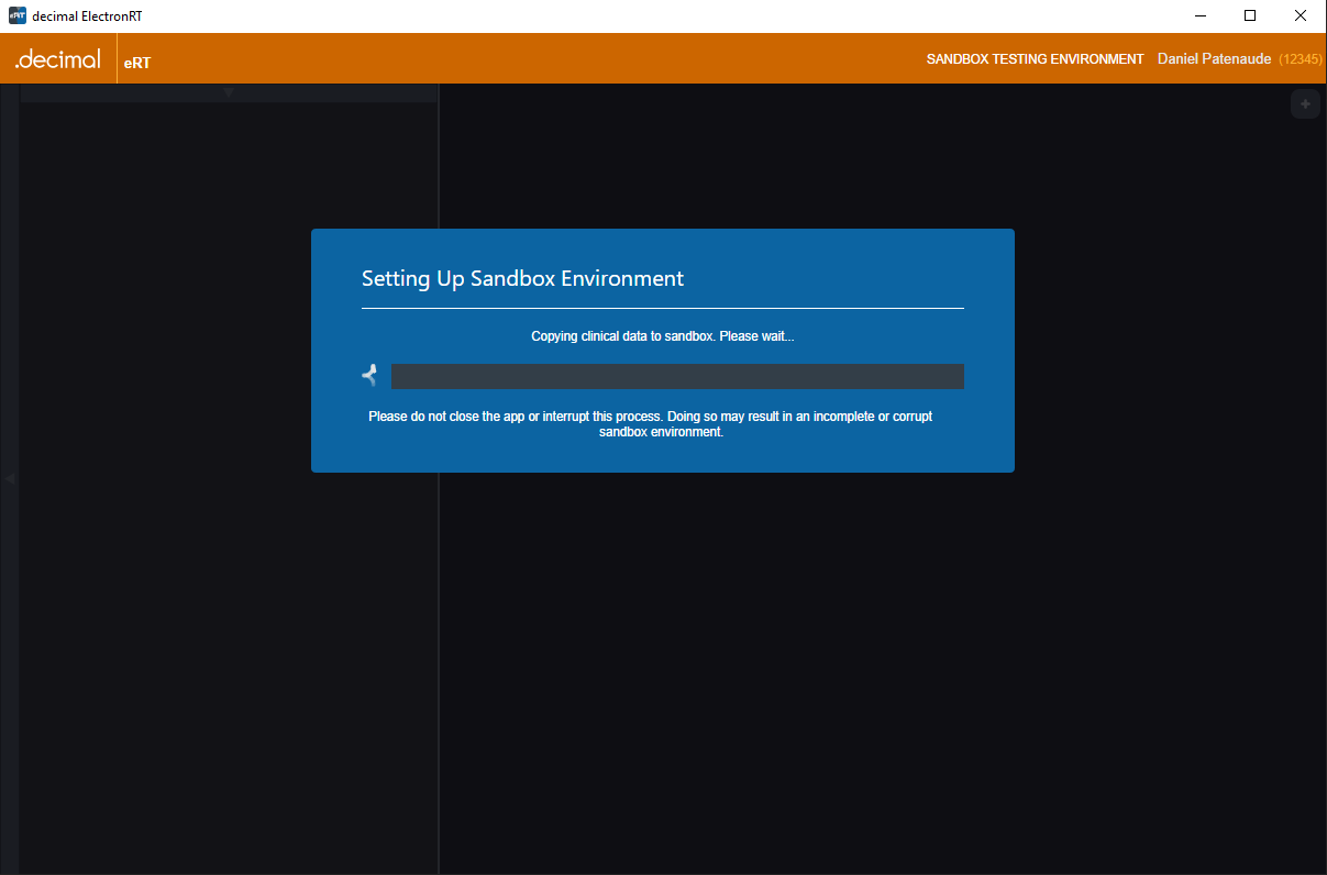
The first time the Sandbox environment is created the Clinical site data will be imported into the Sandbox data store. Then any clinical patients flagged for 'Use in Sandbox' will be copied into the sandbox data store. The patients, courses, and plans will be copied to the sandbox environment exactly as they were last modified/approved in the clinical environment.
Consecutive Sandbox Use
The next time decimal eRT in Sandbox mode is used the application will detect an existing sandbox installation and will prompt the user for how to proceed:
- Use the existing sandbox:
- The existing sandbox environment will be used exactly how the user last left it
- Make new sandbox:
- This will completely wipe the existing sandbox environment and reimport the Clinical data following the First Time Sandbox Use process.
- Note: This step can not be undone and all sandbox data will be completely removed. Ensure to manually backup your patient data prior to performing this action if you believe you may need the previous sandbox environment.
decimal eRT Settings
The following settings are present within the decimal eRT settings UI accessed within the View → Settings menu:

App Settings
- Landing Page
- Allows the user to specify whether or not to view the application landing page when decimal eRT is opened.
- Inactivity Timeout
- Specifies the time out period (in minutes) to automatically log the user out of the application. Timeout is based on mouse/keyboard interaction within the user interface. Note: This inactivity timeout is different than the user session token received from the decimal Launcher.
- Default DICOM Directory
- Sets the default DICOM import directory. This directory will be used each time a DICOM import is attempted.
- UI Theme
- Set the visual theme of the application (Note: the 'blue' theme is the currently supported theme; a 'dark' theme is available, but is a deprecated theme and not routinely updated at this time).
Local Disk Cache
The local disk cache is where calculation results are stored on the client computer. The recommended storage size for this cache is 25GB.
Users can choose to manually clear the disk cache or let it clear oldest data as the cache fills. Refer to Data Management Storage and Caching for more information.
Network Disk Cache
The network disk cache is where calculation results are stored on a network drive where all users can access. If calculation data is not found on the local client cache, the network cache will be checked for the calculation results. The recommended storage size for this cache is 25GB.
Users can choose to manually clear the this cache or let it clear oldest data as the cache fills. Refer to Data Management Storage and Caching for more information.
Patient Storage
The directory for the decimal eRT patient database and file store. The default location is a folder above the application directory installed via the decimal Launcher on the local workstation. Setting this to a shared network resource allows multiple users to share a common patient database.
Refer to Data Management Storage and Caching for more information.