User Tools

Site Tools


decimal3d:instructions_for_use:customer_walkthrough

This is an old revision of the document!


Walk-through

This walk-through is intended to be an easy to follow step-by-step guide for a “standard clinical electron” set-up, design and order electron apertures. It should be noted that the values provided are not intended to represent clinical guidelines and in no way be considered a recommendation for values that are appropriate for clinical use. The intent is that after completing this walk-through the user will have gained the knowledge an understanding of many of the details and much of the information to complete a clinical electron set up utilizing the decimal3D App. With this information the user will be able to to complete the process using the clinical protocols and requirements for your facility to set-up a clinical electron treatment, design the electron aperture and then order the electron aperture from .decimal.

  1. Have the physician outline the treatment area in the exam room
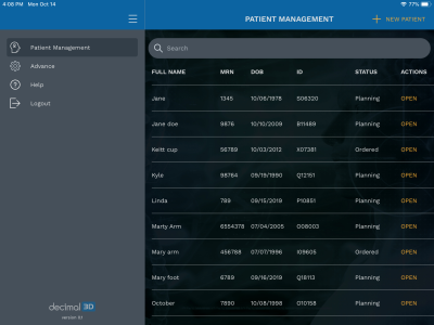
  2. Open the decimal3D app on the iPad and login with user name and password:decimal3d:instructions_for_use:img_0021.png?600|}}
  3. Bring the patient to the simulator or treatment room
  4. Select New Patient in the top right hand of the Patient Management Screen :decimal3d:instructions_for_use:img_0022.png?600|}}
  5. Enter Patient Name
  6. Enter Date of Birth from drop dwon
  7. Select patient Gender from drop down
  8. Enter MRN (Medical Record Number)
  9. The user may select the enter the Physician if desired
  10. Select OK that the patient is entered successfully
  11. In the top right hand corner select New Scan
  12. Select the New Scan button on the left hand side
  13. On the right hand side of the gantry/table with the iPad parallel to the floor and abut the iPad to the couch and press the Align button
  14. Place the area to be scanned in the box. The area to be scanned should appear in all red. This will require the user to stand approximately a half meter away from the patient. A scan be obtained by either doing one short scan of the area to be treated or doing a more detailed scan obtaining a larger area, still including the area to be treated. Press the Scan button to start the scan. Then press again to stop the scan
  15. As the scan is rendering it will appear white
  16. One the scan is done processing select the Accept Scan if the scan is acceptable
  17. If it the scan is not acceptable select the New Scan button on the left-hand side to start a new scan
  18. Choose the machine name from the scroll wheel. By default the first scan is labeled Scan 1 (following scans are labeled consecutively). The user may choose to change the scan name if desired. Choose Submit when done
  19. Select New Contours
  20. Draw Contour will be automatically selected on the next page. Using either the Apple Pencil or a finger dwell on the scanned image for a second and begin to digitize the area to be treated. The outlined traced area will now show up in green.
  21. Once the user has completed the digitizing they may adjust the contour by selecting Adjust Contour. To do this the user needs to place the Apple Pencil or finger close to the area that needs to adjusted and slide it to where it should be
  22. If the user is satisfied with select the Finish option on the right hand side of the screen. The user can now name the contour or leave the name at the default. Choose Submit when done
  23. To create the beam user must first select contour they want to place the beam on and then select the orange Next in the bottom left of the screen
  24. The user will then tap on the scan where they want to place the entry point and select the orange Next
  25. The user can then adjust the rotation as necessary to place the beam enface or in the appropriate position as desired and select the orange Next
  26. Choose the desired SSD. Then select the Next
  27. The user can then adjust the cone size if desired. The smallest cone size will automatically be chosen. The user may also rotate the view to verify that collisions will be avoided
  28. The user may then adjust any angles that need to be adjusted as well as fill in any free form text that needs to be sent to the Record and Verify (R&V) system. When the user is satisfied they may select Saveand proceed to name the beam or leave the name at the default{{ :decimal3d:instructions_for_use:img_0057.png?400 |}}
  29. At this point the user may proceed to ordering the cutout
  30. The user must select the shipping priority. Once this is done they may select Done and the information will be securely sent to .decimal and the cutout manufactured
decimal3d/instructions_for_use/customer_walkthrough.1577816191.txt.gz · Last modified: 2021/07/29 18:21 (external edit)