This is an old revision of the document!
Table of Contents
Tutorials
Launching Astroid
The Astroid Launcher will house the various applications that will be used as part of the Astroid Treatment Planning system. Any updates to these applications will automatically be deployed to the Launcher. The user will be notified that there is an update or a new version that will need installation once they have chosen an application. This will ensure that cloud version of Launcher and the local version of Launcher remain synchronized. Use the following steps to open the Launcher and launch the Astroid Planning App:
- Click the blue Login button
- Select your realm from the list of available realms
- From the left side tool bar select the application you would like to launch
- Click the blue Launch button
- If there is an updated version of this application, the Launch button will not appear and instead an Install button will be available. Click this to allow the latest version to install. After the latest version is installed, the blue button will revert back to Launch, which you can now click
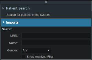
- This will open the Astroid Planning application and bring you directly to the main patient search screen
- You may now proceed with opening a current patient or importing a new patient
Uploading DICOM Patient Files
The Astroid Planning App stores a list of DICOM files (only CT Image Set and Structure Set files are supported at this time) that are available and ready for Import. There are several approaches that can be used to upload DICOM files into this list.
DICOM Receiver Service
For clinical users, a DICOM receiver is generally installed, allowing for direct exporting from contouring software or other planning systems for use within Astroid. In such cases, this DICOM receiver service will be pre-configured to upload the incoming files directly to Thinknode and will also create the records necessary for the DICOM files to be populated into the Astroid Planning App list of available Imports.
Uploading using the Planning App
DICOM files can also be uploaded directly from the Astroid Planning App. The steps below describe the process in detail.
-
- All DICOM files found in the selected directory will populate in the list field
- If the file list appears correct, click the blue Upload button in the bottom right corner to start the Upload
- Once the file(s) finished uploading they will appear in the list of available files, click back on the Search Files sub-block to return to the list of available files
Bulk Importing using Python
Note: This section requires the user to be familiar with python and the existing .decimal python libraries.
Importing a new patient into the Planning App requires taking a local DICOM directory and posting each of the files through the Dicom App utilizing Thinknode. Each DICOM patient is posted to the Thinknode ISS and an entry is then added to the thinknode RKS that allows the Planning App to see that a new patient has been added. The steps below explain how to upload patient DICOM files using the open source python Astroid Script Library.
- From the .decimal GitHub repository open and edit the post_dicom_patient_rks.py python file.
- Ensure the thinknode.cfg file is set appropriately for your user, account, and realm.
- Edit the following line to point to the directory in which the DICOM patient files are located (note: all DICOM files in this directory will be uploaded):
# Post patient data into ISS
obj_list_id = dicom.make_dicom_object_from_dir(iam, 'F:/Datasets/demo-patient/prostate')
- Run the script and allow the patient to upload to thinknode ISS. After the DICOM patient files are uploaded to ISS, an RKS entry will be created for the Planning App to recognize it as a DICOM file that is available for import.
Importing Patient Data
Now that a patient has been uploaded from DICOM, the Planning App should recognize that new patient files are available to import into a Planning patient.
- Open the Astroid Launcher and launch the Planning App from your realm
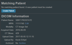
- Select the CT image set from the list of available files for import
- Ensure that the MRN is correct
- Ensure that the date and time displayed in Astroid matched the current date and time in the current Windows OS.
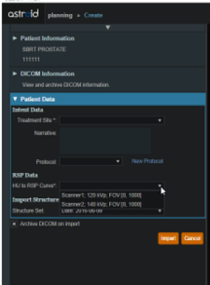
- Fill in the requested Patient Intent, taking care to select the appropriate Treatment Site as this selection contains the template information that will be used during structure set import
- The corresponding structure set (SS) file to import with these images will automatically be selected. The structures will show up below the Patient Data box in the Import structures box (note that the available choices will be automatically filtered based on the structure set DICOM UID information)
- The structures associated with the data set will be seen in a list of the available structures
- Here you may choose whether or not to import each structure by checking or unchecking the box beside each structure name
- Matched, Assigned, and Custom structures are designated with corresponding tags at the end of the structure name in the structure list
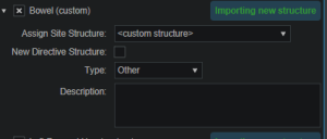
- You may only edit structures that are shown as Custom, which indicates the name did not exactly match a course structure from the Treatment Site template selected above
- For all custom structures, the type is by default set to the value from the DICOM file. If there is no type specified in the DICOM file the type will be set to “Other”, unless it contains the letters “TV” (as in PTV or CTV), in which case it is assigned the type of “Target”; the type may be changed here if needed
- Alternatively you may Assign a Custom structure to a course level template structure using the provided drop down menu (this is useful when structure names contain typos or contour names otherwise do not match your standard site protocols)
- Once all structures have been selected, assigned, and edited as needed, click the Import button to create the patient and import the CT Images and Structures into it
- The patient is now created and all available data has been imported
- Click on the Back to Import button to return back to the Imports task
Structures in the Data Model
There are multiple levels that various structures can live at. Each level and structure type will effect how the structure will relate to the plan. Refer to the Structure Data Model Guide for more details.
Courses
Overview
The Astroid patient data model uses a hierarchy of items to model the real world workflow patterns of the radiotherapy treatment process. Please refer to the Heirarchy (Data Model) page if you are not familiar with these concepts.
During patient creation (i.e. Importing) a patient record is created containing a Course and a Patient Model. During Import the required data for the Course and Patient Model are entered, however, the Course remains incomplete. The Course will still require physician directive information including the breakdown of the treatment Prescriptions and (optionally) the specification of Clinical Goals. Before creating a Plan this information must be entered. Once the Prescription is complete, plans can be created. The following sections provide a walk through for completing the Course information.
Prescriptions are cumulative. For example: when adding a second prescription, it is assumed that the highest dose from the first Rx has already been delivered to the target for the second prescription. Therefore, the total dose to all targets in the second prescription will have the first prescription's highest dose added.
Completing the Course Prescription
- From the Patient list, select a patient to be opened by clicking the patient row
- The Prescription information is part of the Course, which can be edited by clicking on the blue edit button beside the Course label in the patient overview
- The Course Prescription information is mandatory to fill out in order to proceed with planning and at a minimum one Prescription must be created (Clinical Goals are optional)
- The Course contains some basic information as well as two blocks of data: Clinical Goals and Prescriptions
- Clinical Goals are used fill in the “goals” (objectives) the physician would like to see achieved by the plan
- To add a goal, simply select click Add Structure and select a desired structure (the choices in the structure drop down will be set by the treatment site template) to which goals should be added
- The user can create goals for tumor volumes as well as Organs at Risk (OAR) and can specify minimum dose, maximum dose, mean dose, and volume based (DVH) goal types
- The Clinical Goals will be used for reporting purposes to describe the physician's intent for the treatment; these do not affect the calculation or plan directly
- The second major part of the Course are the Prescriptions
- This is where the user will fill in the number of fractions and the prescription dose that specified by the physician
- Note that a prescription must be created in order to start the planning process
- Click New Prescription under Prescriptions to create a new empty phase
- The Prescription label and description are free text fields that the user can enter to help identify a particular phase as needed
- A color may be selected for the Phase to aid in identification as well
- Once all Prescription information has been entered, click the blue Add button to complete the Prescription
- Additional prescriptions may be added at this point if needed (for example, for a treatment needing a base treatment and a boost)
- The Course should now be complete
- Click on the Done button to return back to the Patient Overview
Patient Models
Once the Course has been completed the next block will be the Patient Model. The Patient Model contains a single CT image set and all contour variants (targets and organs at risk) associated with these images.
About Patient Models
- Patient Model: captures the state (anatomy) of a patient at a certain point in time. Each Patient Models contains a single Image Set (typically CT) and all contour (structure) variants associated with these images. Each unique Image Set imported into the patient should produce a new Patient Model. Each unique structure set imported into the Patient Models should produce new contour variants for each unique contour. Each contour may have only a single “active” variant and the plan will automatically update based on the selection of the active variant.
- Variant: A specific model of a target, OAR, or other structure. A physician may provide an initial target contour and a treatment plan might be generated using this information. The physician may later (using the same CT image set) provide a revised target contour. Rather than import this revision as a new structure or override the original, you may specify this new contour as a variant of the original and the plan will automatically update based on the selection of this new active variant (note each contour/structure may have one or many variants, but only a single variant can be designated as “active”).
Structure Data Model
There are multiple levels that various structures can live at. Each level will effect how the structure will relate to the plan.
Note:
- The assignment of structure type will determine the types of constraints or objectives you can put on the structure.
- Only structures with a Type of Target can be used as Beam Targets
- Site level, Course level and Custom structures can be shared within plans on the same patient
Site Level Structures
Site level structures are predefined templated structures. The user is not allowed to edit any aspect of a Site Level structure. Site level structures may be used for prescriptions as long as they have been designated as a Target.
Course Level Structures
Course level structures are not predefined templated structures (Site Level Structures). Course level structures may have certain properties edited within the planning user interface (e.g.: their type). A structure may be assigned as a Course level structure by choosing the box “New Course Structure” option at the time of import for any structure that does not automatically match a Site Level Structure. 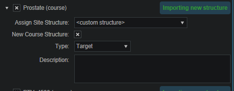 Structures that have been changed to Course level will have be designated as such by the word “course” appearing in parentheses beside the structure name during import. This is useful when a structure was misnamed during the contouring process. Course level structures that have been designated as Target structures can also be used for prescriptions. Any structure with TV as part of its name will automatically be designated as a Course Level structure.
Custom Structures
Custom structures show up at the Patient Model level. These are structures that were not part of the templated structures nor assigned as a Course Level structure. The user has the option to edit the properties of a custom structure from within the Patient Model task. 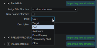
Plan Level Structures
Plan level structures are structures created with the Astroid TPS. These structures are derived from existing structures (e.g.: expansions, combinations). See Patient Geometry on how these are created.
Structure Types When Used in Optimization Constraints and Objectives
The structures type determines the options available to the user when specifying constraints and objectives for the treatment plan optimization (refer to Optimization Constraints and Optimization Objectives for definitions of Constraints and Objectives). Below explains the structure types and options available for each type during optimization:
Non-Target Structures
For structure types that are not Target or Other the user only has the ability to set constraints and objectives that drive the dose downward.
Target and Other Structures
For structure types that are Targets and Other the user has the ability to set constraints and objectives that drive the dose upward and downward.
Working with Patient Models
Within Astroid the planner has the ability to view the Patient Model details and edit certain structures in a limited capacity.
- A Patient Model contains data relating to the image set such as the number of slices, who imported the image set, the import date and the UID.
- Structures not defined in the site config (i.e. custom structures) are denoted with a “c” beside it. These structures have the ability to be edited in a limited capacity. The planner may choose to change the structure variant, color, and structure type. The planner may also choose to enter any notes that may be helpful at this point.

Creating a Plan
- The point has now been reached where a Plan can be created
- Click on the blue Add Plan link under the Patient Model to create a new plan
- Note that the Base Plan option is used to specify whether an empty plan should be created or if the new plan should be pre-filled using the selected Plan Template (details on Plan Templates can be found here)
- Click on the blue OK button when finished and the Plan has been created
- Open the plan and begin the planning process by clicking on the blue Open button next to the new plan
- Note that users are free to have as many plans as desired within a the Patient Model and each Plan will specify which portion of the Course Prescriptions it is attempting to implement
Dose Grid
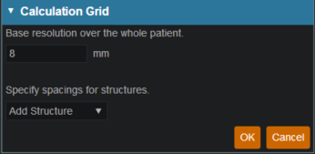
Astroid utilizes a calculation grid that allows for local grid resolution to be specified on a per structure basis. This allows for improved optimizer performance in terms of both speed and resultant plan quality. A uniform sized base calculation grid is created over the entire patient structure. This base resolution can generally be set to a size much larger than the value needed for accurate clinical dose resolution. The user can then reduce the grid sizes in critical areas, generally the high gradient regions and target areas that require homogeneous dose, by assigning appropriate structures a smaller grid spacing value. A common configuration is to use a base resolution of 8mm, 4mm within critical OARs and the PTV/CTV and 2mm in a thin (rind) region surrounding the PTV. This provides sufficient dose information for the optimizer to maintain uniform dose to targets, drive down dose to OARs, and achieve steep dose fall at the boundaries of targets and healthy tissue. An example of constructing such a grid is given below.
- Open the Calculation Grid block
- The default base resolution is set in the site specific configuration settings and is applied throughout the entire patient
- If you want to use a smaller grid in a target or OAR choose that structure from the dropdown and then specify the desired resolution
- Note that allowable resolutions are scaled down by powers of 2 from the base resolution by using the +/- on either side of the region spacing setting
- Once the appropriate regions and resolutions have been set, click Ok to save the calculation grid
- The Calculation Grid block can be revisited at any time to adjust the grid if needed


