planning:userguide:tutorials:range_compensators
Table of Contents
Creating a Range Compensator
Note: Range compensators can only be added to SOBP beams.
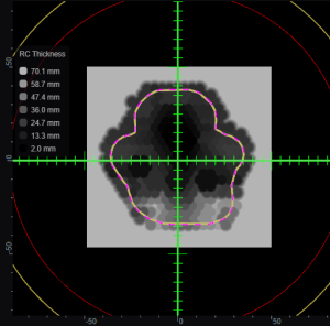
A range compensator is automatically added for any snout that has range compensator information defined for use in the site specific machine model. The site model also includes the maximum and minimum possible thickness values, the material, and the extents (outer dimensions) of the range compensators for each snout.
Re-using Existing Hardware
Geometric or Dose Based
- Astroid has two algorithms to design proton range compensators, a standard geometric approach and a dose based option. Each is explained below.
- Geometric:
- Ray tracing is used to determine the water equivalent depth (WED) at the distal surface of the target volume throughout the entire treatment field
- Using this data, the appropriate thickness of range compensator material is added to each rayline such that protons will stop at the distal target surface (thickness = r90 - WED)
- This is the standard design approach for range compensators in nearly all other planning systems
- Dose Based:
- This approach begins with a standard geometric design
- Then the actual dose delivered from this field using the current compensator is computed
- Ray tracing is then used to compute the distance between the actual (computed) 90% isodose surface and the distal target surface throughout the entire field
- Material is then added or subtracted from the range compensator for each rayline, based on the difference in depth between these two surfaces
- The process repeats from step 2 for a predefined number of iterations (defined in the site info, and should typically be between 3-10)
Range Compensator Parameters
- The range compensator calculation uses a distal range margin that is the addition of the user-defined “Range Margin Distance” and the “Range Margin Percentage” of the beam range. The “Smear Radius” is a distance over which to reduce heights of nearby drill points to avoid narrow valleys in the compensator surface and improve treatment robustness. All drill points are dropped to the lowest height neighbor within this radius. The “Target Distal Dose” is the dose value that the range compensator calculation will try to achieve on the distal edge of the target (most typically 90%).

planning/userguide/tutorials/range_compensators.txt · Last modified: by 127.0.0.1


