Table of Contents
Electron Block Creation
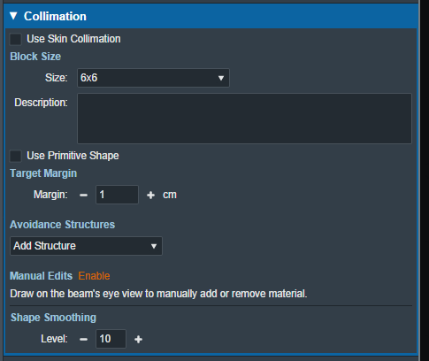
Here the user can create and edit Electron Blocks for the selected beam as well as edit values for an existing block.
Block Size
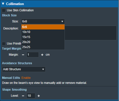
- Size: Select the block size. The list of available block sizes is derived from the list of applicator (cone) sizes available for the selected machine. Applicator sizes can be enabled and disabled from editing the machine data in the site configuration.
Note: When first creating a beam the eRT app will auto calculate the smallest block that will fit the current aperture shape.
Note Selecting a block size that is too small for the aperture shape will cause an error that will not allow the creation/saving of the beam until an appropriate size is selected.
- Description: An optional description for this block used to identify it.
Target Margin
- Margin: The value (in cm) of the margin around the target structure as projected to isocenter. A negative margin can be used to specify a contraction around the beam target while positive values will cause an expansion. The default block target margin can be configured in the Site Configuration Machine Settings.
Note: The app will automatically recalculate and display changes to the block as the margin is edited.
Primitive Shape
Instead of using the geometric target, the user may use a primitive shape as the base block opening instead. The user can choose the shape (square, circle, rectangle, or oval) and the dimensions at isocenter.
Avoidance Structures
The user may select one or more structures in the structure list here to add as an avoidance structure. Avoidance structures will decrease the block opening to remove all areas within the projection of the structure.
 Fig. 6: Avoidance structure selection
Once the structure is selected you will be able to set the values for how it should be avoided. Including:
- Avoidance Margin: required, sets the margin of avoidance around the selected structure's projection to the isocenter plane.
 Fig. 7: Selected avoidance structure
- Force min target margin: disabled by default, when enabled it will force a minimum margin around the target taking priority over the settings of the avoidance structure.
For example: As shown below, there is an overlap between the margin set for the avoidance structure and our target structure. Since “force min target margin” is disabled, the avoidance margin has priority over the target.
 Fig. 8: Force min target margin is off
If the user decides that the target should have priority over the avoidance structure we can enable the “force min target margin” and set a min margin for our target. As you can see below the min margin set takes priority over our avoidance margin and there is no more overlap.
 Fig. 9: Force min target margin is on
- Occlude by target: The user may also choose to occlude the structure by the target or not by using the “Occlude by Target” option. For the following examples we will use the Spinal Cord as it shows a dramatic example of differences of using or not using the “Occlude by Target” option. A 5mm margin was applied to the Cord for the following examples.

- Checking the “Occlude by Target” option makes the calculations account for the relative depth positions of the target and avoidance structure when determining the area to avoid. More specifically, the visible portion of the target (target volume that is in front of the avoidance structure) will not be blocked by the aperture. Note that just the inferior edge of the Cord is blocked by the aperture as this is the only portion that is visible (not behind the target) and the part of the Cord that is behind the PTV is not blocked.

Manual Edits
By default manual editing of the block shape it disabled, but a user can elect to enable the ability to manually change the block shape.
 Fig. 10: Enabling manual edits
Once manual editing has been enabled you will see the cursor update to reflect the editing tool. You can choose to edit with the Brush cursor or by drawing straight lines using the Line tool. Both take in the radius that can also be set by the user to alter the size of the editing tool.
Note: Drawing on the “Exterior” of the aperture shape will shrink the shape of the block as can be seen below.
 Fig. 11: Shrinking the block shape
Note: Drawing from the “Interior” of the aperture shape will expand the shape of the block as can be seen below.


