
Table of Contents
Electron Bolus Creation
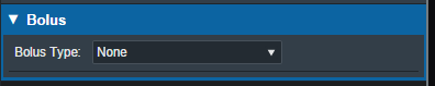
An electron bolus is an optional device for each electron treatment beam. A user is able to add an electron bolus to their beams to help improve the dose conformality to the distal target surface. The four options for bolus types in the decimal eRT app are fully defined below.
Optimized Thickness Bolus
The first option a user has for creating a bolus for the selected beam is an optimized thickness bolus. The goal for an optimized bolus is to best fit the specified Planning Isodose level of the computed beam dose to the distal surface of the target structure. The application provides reasonable default parameters for designing such a bolus, so that in most cases, the user can simply click the “Generate Bolus” button and the application will design a suitable bolus automatically. Once the application has finished calculating, the bolus will get added to the beam.
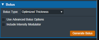
For complex and challenging plans, a user can also access advanced options to modify an existing bolus or create a new one from scratch.
In the advanced options you can view and manage various operators to augment the design of the bolus. The following operators are available:
Construction Operators (only available when first creating a new bolus):
- Automated Marching
- This operator constructs the proximal bolus surface using a series of incremental steps. Each step consists of a small thickness reduction at the optimally selected locations, followed by a hot spot damping step, in which the slopes of the bolus surface are reduced in areas where high dose values are found.
- Geometric Sequence
- This selection performs the following sequence of operators: Create, Smooth, Truncate.
- Single shift Sequence
- This selection performs the following sequence of operators: Create, Smooth, Isodose Shift, Smooth, Truncate.
- Double Shift Sequence
- This selection performs the following sequence of operators: Create, Smooth, Isodose Shift, Smooth, Isodose Shift, Smooth, Truncate.
- Create
- This operator constructs the proximal bolus surface by computing the difference between the physical depth to the distal PTV surface and the depth of the Planning Isodose level along each ray line of the bolus construction grid (for ray lines not intersecting the PTV, an extension is performed using the heights of the points that do intersect, which helps ensure the PTV edges are adequately covered).
Modification Operators (only available after a construction operator has been performed):
- Smooth
- This operator performs a Gaussian type smoothing on the current bolus proximal surface, which uses a distance weighted average of the neighboring point heights to compute a new height for each bolus surface point.
- Isodose shift
- This operator updates the bolus proximal surface by using the dose results with the current bolus in place to adjust the bolus heights by the difference between the position of the Planning Isodose contour and the position of the distal PTV surface.
- Truncate
- This operator updates a bolus proximal surface by reducing the height of the bolus in the region outside the Block Outer Border. The height is reduced to be slightly above the highest point in the modulated region. It should be mentioned that truncating a bolus may limit the ability to shift points upward (increase in thickness) when performing manual isodose shift operators after the truncate.
- Specified Shift
- This operator updates a bolus proximal surface by shifting all points (even the region beyond the Block Outer Border) by the specified distance.
- Intensity Modulation
- This operator manually adds an Intensity Modulator device to the beam. If multiple Intensity Modulation operators are added in the operator list, then the results of the multiple iterations of the modulation calculation are combined to produce a single Intensity Modulator device for the beam.
If an operator is selected from the list the UI will update to show the options for that operation. Once the options have been finalized the user can add the operator to the list which will re-compute the bolus and IM devices for the beam.
Below is an example of adding the automated marching to a new bolus:
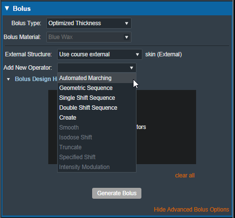 Fig. 3: New bolus operator options
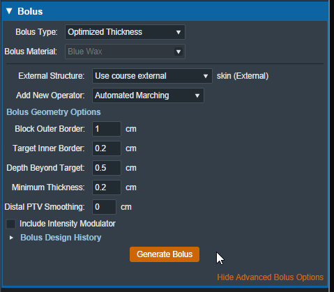 Fig. 4: Adding an automated marching operator
The advanced optimized thickness bolus design parameters allow the user to fine tune the bolus design for specific operators. These options include:
- Block Outer Border:
- The distance to extend the bolus surface beyond the block/collimator perpendicular to the CAX.
- Target Inner Border:
- Specifies the distance to offset the target projection inward when defining the region over which initial construction and smoothing operators act. This is used to reduce the effects that the rapid PTV height changes near the target edges can have on the construction and smoothing operators.
- Depth Beyond Target:
- The beams-eye-view distance past the selected target (along the CAX direction) at which the patient-side surface will be truncated.
- Minimum Thickness:
- The minimum allowable thickness of the bolus as measured along a beam aligned rayline.
- Distal PTV Smoothing:
- The smoothing ball radius used to smooth the target structure. A larger radius will result in more smoothing but will also cause a greater deviation of the target from the original structure. Note that setting this value to 0 mm will result in no smoothing for the target structure.
- Smoothing Weight: (Smoothing operator only)
- The exponential smoothing weight coefficient (smaller value increases smoothing)
- Smoothing Size: (Smoothing operator only)
- The smoothing distance factor (larger values spread the smoothing range further)
- Additional Thickness: (Specified Shift operator only)
- The thickness to add to the bolus proximal surface (use a negative value to reduce height)
Additionally by selecting the “Bolus Design History” you can see a list of every step in the bolus design. The last step is removable individually, and there is also the option to clear all steps and start from scratch.
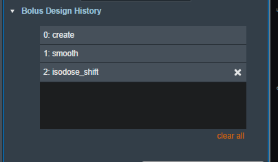 Fig. 5: Bolus design history list
When designing an optimized thickness bolus, you also have the option to select the patient external structure. By default, this is set to the external structure defined in the course.
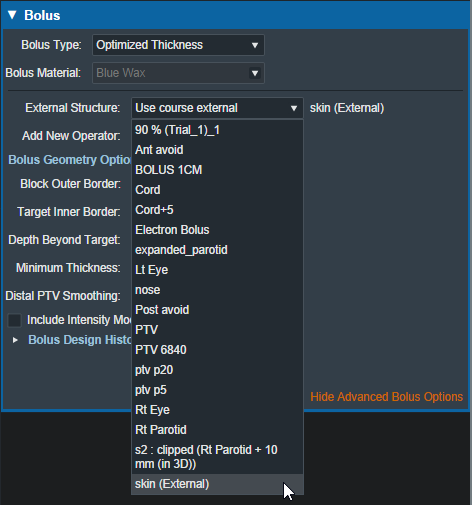 Fig. 6: Bolus external structure selection
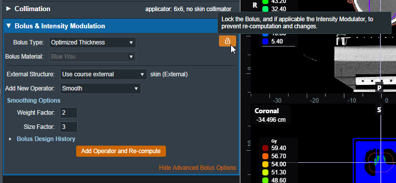
If you want to make changes to the beam without having the optimized thickness bolus re-calculate, there is a lock button that prevents the optimized bolus from changing during other beam changes (e.g.: changing the block shape will normally cause the bolus to re-compute). This will lock the bolus design and prevent any changes. If anything in the beam is changed after locking the bolus and the bolus is unlocked then the bolus will be re-computed using the new beam parameters.
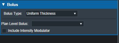
Uniform Thickness Bolus
Uniform Thickness Bolus devices are designed at the plan level, but they must be added to each intended beam individually to ensure the computed dose accounts for the presence of the bolus in the beam path.
Structure as Bolus
The user also has the option to use existing plan structure as a bolus. Once this option is selected, the user will be able to choose the structure from the drop down list and the app will set it as a bolus for this beam.
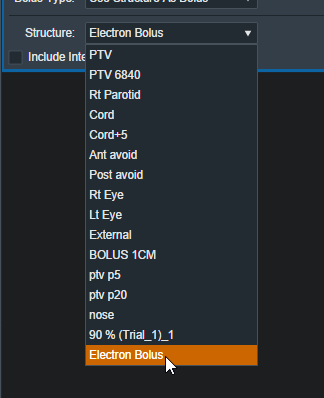 Fig. 9: selecting from the structure list
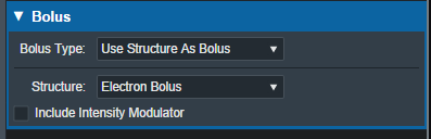 Fig. 10: selecting a Bolus as a structure
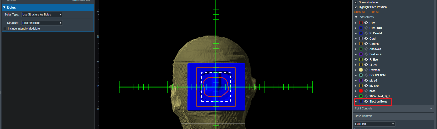
Once the structure is selected the bolus will be added to this beam and dose re-calculated.
Note: The bolus is displayed in the BEV for this beam even though the “Electron Bolus” structure is hidden through the right hand side controls. This shows that the displayed bolus is added as a bolus on this beam and not appearing as a structure.
If you wish to import a bolus that is not currently in your structure list please refer to the DICOM Patient Import section of the user guide for how to re-import a structure set.
Intensity Modulator Device
Additionally if any type of bolus is added to a beam the user is able to also include an Intensity Modulator by selecting the option below any bolus type. The user will then have the option of modifying the dose scaling value applied when calculating the positions and diameters of the intensity modulation pins. The application with calculate the device and display it in the beams UI.
NOTE: In order to add an IMET device the selected beam MUST have a valid bolus.
Circular applicator shapes (e.g.: Siemens 4×4) are not supported for intensity modulators.
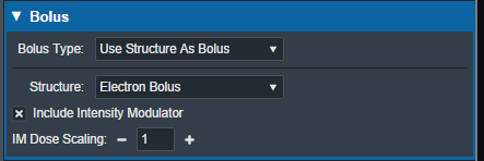 Fig. 12: IM Dose Scaling control
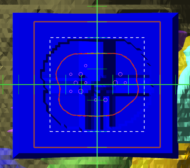 Fig. 12: BEV IMET
As with a bolus, the IM device can be hidden and un-hidden from the display using the beam controls on the right hand size.
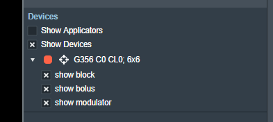 Fig. 14: RHS options to hide/show devices
Users with Elevated Physics level permissions are able to import a user-defined intensity modulation device. The imported device file must be a .csv file with the format: X,Y,Diameter for each pin on a new line. The values must be at the physical block/tray position and the pin diameters must match the supported modulator diameter list.
An example file is:
- im_file_example.csv
0.3,-1.55885,0.352
-0.3,1.55885,0.158
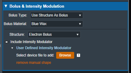 Fig. 15: Option to import user defined intensity modulator file