This is an old revision of the document!
Table of Contents
Electron Bolus Creation
An electron bolus is an option device for each electron treatment beam. A user is able to add an electron bolus to their beams to aid in proper distribution of dose.
There are four options for boluses in the decimal eRT app as defined below:
Optimized Thickness Bolus
The first option a user has for creating an bolus for the selected beam is an optimized thickness bolus. The user can select the “Generate Bolus” option and have the application automatically create an optimized bolus that will best attempt to put the beam's specified isodose level to the distal edge of the target. Once the application has finished calculating you will notice the bolus gets added to the beam.
If the need arises a user can also access advanced options for modifying an existing bolus or create a new one from scratch.
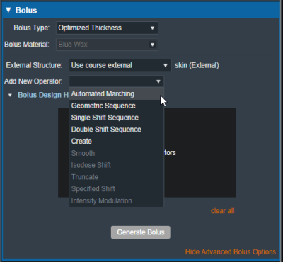
In the advanced options you can add the following operators to augment your bolus:
The following construction operators are only available when first creating a new bolus.
- Automated Marching
- This operator constructs the proximal bolus surface using a series of incremental steps. Each step consists of a small thickness reduction at the optimally selected locations, followed by a hot spot damping step, in which the slopes of the bolus surface are reduced in areas where high dose values are found.
- Geometric Sequence
- This operator constructs the proximal bolus surface by first computing the physical depth to the distal PTV surface along each ray line of the bolus point grid. The initial bolus thickness required at each point is then computed based on the specified prescription value (for ray lines not intersecting the PTV, an extension is performed using the heights of the points that do intersect, which helps ensure the PTV edges are adequately covered). The resulting surface is then smoothed.
- Single shift Sequence
- This operator performs the Geometric Sequence operations and then performs a single Isodose Shift operator and Smooth operator
- Double Shift Sequence
- This operator performs the Geometric Sequence operations and then performs two Single Shift operations
- Create
- This operator constructs the proximal bolus surface by first computing the physical depth to the distal PTV surface along each ray line of the bolus point grid. The initial bolus thickness required at each point is then computed based on the specified prescription value (for ray lines not intersecting the PTV, an extension is performed using the heights of the points that do intersect, which helps ensure the PTV edges are adequately covered).

The following operators are only available after one of the above bolus construction operators have been performed:
- Smooth
- This operator performs a Gaussian type smoothing on the current bolus proximal surface, which uses a distance weighted average of the neighboring point heights to shift each field point. Note that this operator can only be used after at least one construction operation has been performed.
- Isodose shift
- This operator updates a bolus proximal surface by using the dose field results from the current design to adjust the bolus heights by the deviation of the prescribed dose isocontour and the distal PTV surface.
- Truncate
- This operator updates a bolus proximal surface by reducing the height of the bolus in the region outside the Block Outer Border. The height is reduced to be slightly above (2mm-6mm depending on size) the highest point in the modulated region. It should be mentioned that truncating a bolus may limit the ability to shift points upward (increase in thickness) when performing manual isodose shift operators after the truncate.
- Specified Shift
- This operator updates a bolus proximal surface by shifting all points (even the region beyond the Block Outer Border) by the specified distance.
- Intensity Modulation
- This operator manually adds an Intensity Modulator operation to bolus design. Including this operator results in the beam including the Intensity Modulator device. If multiple Intensity Modulation operators are added in the operator list, then that results in multiple iterations of the modulation calculation.
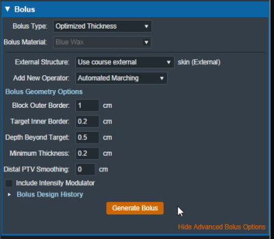
For each operator once it is selected from the list the UI updates to show the options for that operation. Once the options have been finalized the user can add the operator and re-compute for and existing bolus or generate a new one with the selected operator.
Here we have an example of adding the automated marching to a new bolus:
 Fig. 3: New bolus operator options
 Fig. 4: Adding an automated marching operator
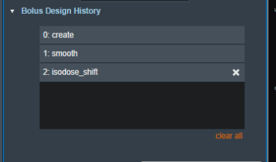
Additionally by selecting the “Bolus Design History” you can see a list of every step in the bolus design, each step is removable individually as well as having the option to clear all steps and start from scratch.
Uniform Thickness Bolus
When adding a uniform thickness bolus the user must add the UTB to all the beams in the plan. Once the plan level bolus has been selected the dose will be recalculated to reflect the new bolus.
Bolus as a Structure
The user also has the option to instead include a bolus as a separate structure in the structure list. Once the option is chosen the user will be able to find the bolus structure from the drop down structure list and the app will set it as the bolus for this beam.
 Fig. 9: selecting from the structure list
 Fig. 10: selecting a Bolus as a structure
Once the structure is selected the bolus will be added to this beam and dose re-calculated as expected.
Note: The bolus is displayed in the BEV for this beam even though the “Electron Bolus” structure is hidden through the right hand side controls. This shows that the displayed bolus is added as a bolus on this beam and not appearing as a structure.
If you with to import a bolus that is not currently in your structure list please refer to the DICOM Patient Import section of the user guide for how to re-import a structure set.
Intensity Modulator Device
Additionally if any type of bolus is added to a beam the user is able to also include an intensity Modulator by selecting the option below any bolus type. The application with calculate the device and display it in the beams UI.
NOTE: In order to add an IMET device the selected beam MUST have a valid bolus.
 Fig. 12: BEV IMET

And as with a bolus the device can be hidden and un-hidden from the display using the beam controls on the right hand size.


