This is an old revision of the document!
Table of Contents
Tutorials
Launching Astroid
The Astroid Launcher will house the various applications that will be used as part of the Astroid Treatment Planning system. Any updates to these applications will automatically be deployed to the Launcher. The user will be notified that there is an update or a new version that will need installation once they have chosen an application. This will ensure that cloud version of Launcher and the local version of Launcher remain synchronized. Use the following steps to open the Launcher and launch the Astroid Planning App:
- Click the blue Login button
- Select your realm from the list of available realms
- From the left side tool bar select the application you would like to launch
- Click the blue Launch button
- If there is an updated version of this application, the Launch button will not appear and instead an Install button will be available. Click this to allow the latest version to install. After the latest version is installed, the blue button will revert back to Launch, which you can now click
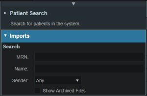
- This will open the Astroid Planning application and bring you directly to the main patient search screen
- You may now proceed with opening a current patient or importing a new patient
Uploading DICOM Patient Files
The Astroid Planning App stores a list of DICOM files (only CT Image Set and Structure Set files are supported at this time) that are available and ready for Import. There are several approaches that can be used to upload DICOM files into this list.
DICOM Receiver Service
For clinical users, a DICOM receiver is generally installed, allowing for direct exporting from contouring software or other planning systems for use within Astroid. In such cases, this DICOM receiver service will be pre-configured to upload the incoming files directly to Thinknode and will also create the records necessary for the DICOM files to be populated into the Astroid Planning App list of available Imports.
Uploading using the Planning App
DICOM files can also be uploaded directly from the Astroid Planning App. The steps below describe the process in detail.
-
- All DICOM files found in the selected directory will populate in the list field
- If the file list appears correct, click the blue Upload button in the bottom right corner to start the Upload
- Once the file(s) finished uploading they will appear in the list of available files, click back on the Search Files sub-block to return to the list of available files
Bulk Importing using Python
Note: This section requires the user to be familiar with python and the existing .decimal python libraries.
Importing a new patient into the Planning App requires taking a local DICOM directory and posting each of the files through the Dicom App utilizing Thinknode. Each DICOM patient is posted to the Thinknode ISS and an entry is then added to the thinknode RKS that allows the Planning App to see that a new patient has been added. The steps below explain how to upload patient DICOM files using the open source python Astroid Script Library.
- From the .decimal GitHub repository open and edit the post_dicom_patient_rks.py python file.
- Ensure the thinknode.cfg file is set appropriately for your user, account, and realm.
- Edit the following line to point to the directory in which the DICOM patient files are located (note: all DICOM files in this directory will be uploaded):
# Post patient data into ISS
obj_list_id = dicom.make_dicom_object_from_dir(iam, 'F:/Datasets/demo-patient/prostate')
- Run the script and allow the patient to upload to thinknode ISS. After the DICOM patient files are uploaded to ISS, an RKS entry will be created for the Planning App to recognize it as a DICOM file that is available for import.
Importing Patient Data
Now that a patient has been uploaded from DICOM, the Planning App should recognize that new patient files are available to import into a Planning patient.
- Open the Astroid Launcher and launch the Planning App from your realm
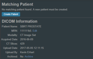
- Select the CT image set from the list of available files for import
- Ensure that the MRN is correct
- Ensure that the date and time displayed in Astroid matched the current date and time in the current Windows OS.
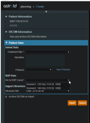
- Fill in the requested Patient Intent, taking care to select the appropriate Treatment Site as this selection contains the template information that will be used during structure set import
- The corresponding structure set (SS) file to import with these images will automatically be selected. The structures will show up below the Patient Data box in the Import structures box (note that the available choices will be automatically filtered based on the structure set DICOM UID information)
- The structures associated with the data set will be seen in a list of the available structures
- Here you may choose whether or not to import each structure by checking or unchecking the box beside each structure name
- Matched, Assigned, and Custom structures are designated with corresponding tags at the end of the structure name in the structure list
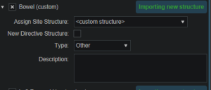
- You may only edit structures that are shown as Custom, which indicates the name did not exactly match a course structure from the Treatment Site template selected above
- For all custom structures, the type is by default set to the value from the DICOM file. If there is no type specified in the DICOM file the type will be set to “Other”, unless it contains the letters “TV” (as in PTV or CTV), in which case it is assigned the type of “Target”; the type may be changed here if needed
- Alternatively you may Assign a Custom structure to a course level template structure using the provided drop down menu (this is useful when structure names contain typos or contour names otherwise do not match your standard site protocols)
- Once all structures have been selected, assigned, and edited as needed, click the Import button to create the patient and import the CT Images and Structures into it
- The patient is now created and all available data has been imported
- Click on the Back to Import button to return back to the Imports task
Structures in the Data Model
There are multiple levels that various structures can live at. Each level and structure type will effect how the structure will relate to the plan. Refer to the Structure Data Model Guide for more details.
Courses
Overview
The Astroid patient data model uses a hierarchy of items to model the real world workflow patterns of the radiotherapy treatment process. Please refer to the Heirarchy (Data Model) page if you are not familiar with these concepts.
During patient creation (i.e. Importing) a patient record is created containing a Course and a Patient Model. During Import the required data for the Course and Patient Model are entered, however, the Course remains incomplete. The Course will still require physician directive information including the breakdown of the treatment Prescriptions and (optionally) the specification of Clinical Goals. Before creating a Plan this information must be entered. Once the Prescription is complete, plans can be created. The following sections provide a walk through for completing the Course information.
Prescriptions are cumulative. For example: when adding a second prescription, it is assumed that the highest dose from the first Rx has already been delivered to the target for the second prescription. Therefore, the total dose to all targets in the second prescription will have the first prescription's highest dose added.
Completing the Course Prescription
- From the Patient list, select a patient to be opened by clicking the patient row
- The Prescription information is part of the Course, which can be edited by clicking on the blue edit button beside the Course label in the patient overview
- The Course Prescription information is mandatory to fill out in order to proceed with planning and at a minimum one Prescription must be created (Clinical Goals are optional)
- The Course contains some basic information as well as two blocks of data: Clinical Goals and Prescriptions
- Clinical Goals are used fill in the “goals” (objectives) the physician would like to see achieved by the plan
- To add a goal, simply select click Add Structure and select a desired structure (the choices in the structure drop down will be set by the treatment site template) to which goals should be added
- The user can create goals for tumor volumes as well as Organs at Risk (OAR) and can specify minimum dose, maximum dose, mean dose, and volume based (DVH) goal types
- The Clinical Goals will be used for reporting purposes to describe the physician's intent for the treatment; these do not affect the calculation or plan directly
- The second major part of the Course are the Prescriptions
- This is where the user will fill in the number of fractions and the prescription dose that specified by the physician
- Note that a prescription must be created in order to start the planning process
- Click New Prescription under Prescriptions to create a new empty phase
- The Prescription label and description are free text fields that the user can enter to help identify a particular phase as needed
- A color may be selected for the Phase to aid in identification as well
- Once all Prescription information has been entered, click the blue Add button to complete the Prescription
- Additional prescriptions may be added at this point if needed (for example, for a treatment needing a base treatment and a boost)
- The Course should now be complete
- Click on the Done button to return back to the Patient Overview
Patient Models
Once the Course has been completed the next block will be the Patient Model. The Patient Model contains a single CT image set and all contour variants (targets and organs at risk) associated with these images.
About Patient Models
- Patient Model: captures the state (anatomy) of a patient at a certain point in time. Each Patient Models contains a single Image Set (typically CT) and all contour (structure) variants associated with these images. Each unique Image Set imported into the patient should produce a new Patient Model. Each unique structure set imported into the Patient Models should produce new contour variants for each unique contour. Each contour may have only a single “active” variant and the plan will automatically update based on the selection of the active variant.
- Variant: A specific model of a target, OAR, or other structure. A physician may provide an initial target contour and a treatment plan might be generated using this information. The physician may later (using the same CT image set) provide a revised target contour. Rather than import this revision as a new structure or override the original, you may specify this new contour as a variant of the original and the plan will automatically update based on the selection of this new active variant (note each contour/structure may have one or many variants, but only a single variant can be designated as “active”).
Structure Data Model
There are multiple levels that various structures can live at. Each level will effect how the structure will relate to the plan.
Note:
- The assignment of structure type will determine the types of constraints or objectives you can put on the structure.
- Only structures with a Type of Target can be used as Beam Targets
- Site level, Course level and Custom structures can be shared within plans on the same patient
Site Level Structures
Site level structures are predefined templated structures. The user is not allowed to edit any aspect of a Site Level structure. Site level structures may be used for prescriptions as long as they have been designated as a Target.
Course Level Structures
Course level structures are not predefined templated structures (Site Level Structures). Course level structures may have certain properties edited within the planning user interface (e.g.: their type). A structure may be assigned as a Course level structure by choosing the box “New Course Structure” option at the time of import for any structure that does not automatically match a Site Level Structure. 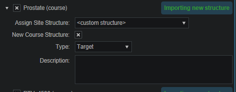 Structures that have been changed to Course level will have be designated as such by the word “course” appearing in parentheses beside the structure name during import. This is useful when a structure was misnamed during the contouring process. Course level structures that have been designated as Target structures can also be used for prescriptions. Any structure with TV as part of its name will automatically be designated as a Course Level structure.
Custom Structures
Custom structures show up at the Patient Model level. These are structures that were not part of the templated structures nor assigned as a Course Level structure. The user has the option to edit the properties of a custom structure from within the Patient Model task. 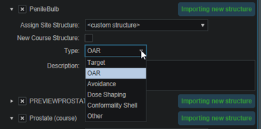
Plan Level Structures
Plan level structures are structures created with the Astroid TPS. These structures are derived from existing structures (e.g.: expansions, combinations). See Patient Geometry on how these are created.
Structure Types When Used in Optimization Constraints and Objectives
The structures type determines the options available to the user when specifying constraints and objectives for the treatment plan optimization (refer to Optimization Constraints and Optimization Objectives for definitions of Constraints and Objectives). Below explains the structure types and options available for each type during optimization:
Non-Target Structures
For structure types that are not Target or Other the user only has the ability to set constraints and objectives that drive the dose downward.
Target and Other Structures
For structure types that are Targets and Other the user has the ability to set constraints and objectives that drive the dose upward and downward.
Working with Patient Models
Within Astroid the planner has the ability to view the Patient Model details and edit certain structures in a limited capacity.
- A Patient Model contains data relating to the image set such as the number of slices, who imported the image set, the import date and the UID.
- Structures not defined in the site config (i.e. custom structures) are denoted with a “c” beside it. These structures have the ability to be edited in a limited capacity. The planner may choose to change the structure variant, color, and structure type. The planner may also choose to enter any notes that may be helpful at this point.

Creating a Plan
- The point has now been reached where a Plan can be created
- Click on the blue Add Plan link under the Patient Model to create a new plan
- Note that the Base Plan option is used to specify whether an empty plan should be created or if the new plan should be pre-filled using the selected Plan Template (details on Plan Templates can be found here)
- Click on the blue OK button when finished and the Plan has been created
- Open the plan and begin the planning process by clicking on the blue Open button next to the new plan
- Note that users are free to have as many plans as desired within a the Patient Model and each Plan will specify which portion of the Course Prescriptions it is attempting to implement
Dose Grid
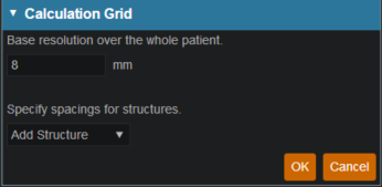
Astroid utilizes a calculation grid that allows for local grid resolution to be specified on a per structure basis. This allows for improved optimizer performance in terms of both speed and resultant plan quality. A uniform sized base calculation grid is created over the entire patient structure. This base resolution can generally be set to a size much larger than the value needed for accurate clinical dose resolution. The user can then reduce the grid sizes in critical areas, generally the high gradient regions and target areas that require homogeneous dose, by assigning appropriate structures a smaller grid spacing value. A common configuration is to use a base resolution of 8mm, 4mm within critical OARs and the PTV/CTV and 2mm in a thin (rind) region surrounding the PTV. This provides sufficient dose information for the optimizer to maintain uniform dose to targets, drive down dose to OARs, and achieve steep dose fall at the boundaries of targets and healthy tissue. An example of constructing such a grid is given below.
- Open the Calculation Grid block
- The default base resolution is set in the site specific configuration settings and is applied throughout the entire patient
- If you want to use a smaller grid in a target or OAR choose that structure from the dropdown and then specify the desired resolution
- Note that allowable resolutions are scaled down by powers of 2 from the base resolution by using the +/- on either side of the region spacing setting
- Once the appropriate regions and resolutions have been set, click Ok to save the calculation grid
- The Calculation Grid block can be revisited at any time to adjust the grid if needed
Proton Beams
Defining treatment beams will be one of the most important tasks within the Astroid planning system. Defining appropriate beams will require users to use their knowledge and experience to properly select many of the parameters that define a treatment beam. These parameters include the target, geometry (isocenter, gantry and couch angles), beamline devices, air gap, and spot placement options. The Beam task utilizes a series of blocks to organize the beam creation process into a common step-by-step sequence. Several blocks are optional as not all beams will use all features. Additionally, it is important to point out that the treatment room & default spot placement parameters are set outside of the individual beam creation tasks as these apply to all beams (however, spot placement parameters can be overridden within each beam if desired). An example of constructing a lateral beam, with the isocenter at the centroid of the PTV is given below to illustrate the features available when defining a beam.
Treatment Room & Mode Type (SOBP or PBS)
- Within the Plan Overview select the Beams block
- If the treatment mode is PBS you can then select and define the plan level PBS Spot Placement Parameters. Edit these parameters to define the spot placement grid for each beam in the plan, noting that individual beams can override these values during beam creation if you so desire
Beam Creation
- The next step is to create the beam by clicking the:
- Create New PBS Beam button for use in PBS treatment rooms
- Create New SOBP Beam button for use in SOBP treatment rooms
- Now we will proceed step-by-step through the various “blocks” to create a complete beam as shown below:
General Settings
The General block is used to set general beam details including:
- Color, Beam Label (or select automatically generate label) and Description
PBS specific
For PBS beams the following additional options will be available:
- Geometric Target is used for approach and device creation. You may choose an existing target or create a new structure. For this example we chose the PTV_7920 as the geometric target. The geometric target will be used to define the extents of the aperture (if used) and will be linked to the isocenter position (if target centroid is selected in the approach block).
- Spot Target is used to define the extent of the PBS spot placements for the beam. The spot target can either match the geometric target, or the user can choose to use the target for the fraction group in which the beam is used (useful for allowing the same geometric beam to be used in multiple fraction groups by simply recomputing the spot positions based on the fraction group target).

SOBP specific
For SOBP beams the following additional options will be available:
- Target is used for approach and device creation, and it can be either a structure or an existing beam.
- If the target selected is an existing beam, the new beam becomes a Patch beam. Thus, the targeted beam becomes a parent thru-beam of the current patch beam (child).
- The patch dose field box is then enabled, allowing users to enter a dose value amount. The parent beam's target will reduced such that any portion receiving a dose from the parent beam that is greater than this amount will be ignored when designing the patch beam range compensator. In other words, the target of the patch beam becomes the target of the parent beam, minus the volume enclosed by the isodose surface (compute only for parent beam) at the defined patch dose value. This patch beam target can be viewed in the Display UI and toggled on and off in the right hand side beam controls.
- Patch beams can also be “chained” beyond a single parent-child pair by creating a beam and selecting the desired patch beam as the target.
- Also note, that once a beam is designated as a patch and added to a fraction group, it cannot be changed back to a standard non-patch beam. In such cases, you must either remove the beams from the Fraction Group first, or a new SOBP beam must be created.
Beam Approach
In the Approach block specify the desired isocenter from the dropdown. You may choose to use the centroid of the Geometric Target (as shown below) or you can select or create a new point to define the location for the isocenter. The gantry angle and couch angles are also entered here as well. Editing these values can be done by typing directly in the provided fields or by using the sliders. The patient in this example is feet first so we will use 90 for the Gantry angle and 0 for the Couch Angle to create a left lateral beam. 
Snout
In the snout block a list of snouts associated with the specified treatment room will be available to choose from. Selecting a snout can change what beamline devices are available based on the facility model in the site info.
Apertures
An option to add an aperture can be found within the Aperture block. An Aperture was not chosen in the PBS beam example. Although selecting an aperture is optional for PBS beam plans, selecting an aperture is required for SOBP beam plans.
- Refer to Creating a New Aperture for detailed instruction
Shifters (PBS)
The Range Shifter block is only available for PBS treatment modes.
- If desired, select the range Shifter to use based on the ones available for the selected snout. If no Shifter is needed as in the example given, the user may go to the next step
Air Gap
Once the beam line devices are defined, we can move to specify the Air Gap distance. The valid air gap range will be listed based on the selected snout. The user may choose any value in this range. 30mm was chosen in the below example.
Beam Spot Placements (PBS)
The Spot Placement block is only available for PBS treatment modes.
- With the beam positioned and any beamline devices put in place, the user is ready view the PBS Spots and adjust the Spot Placement values if needed. The Spot Placement box, if chosen, will allow the user to set new parameters, overriding the spot placement parameters for this one beam if desired. The example below illustrates the message shown when using the spot placement values from the plan level.
Proton DRRs
Proton DRRs do not impact the beam and are used purely for visualization purposes so that you can set the DRR Options to levels that generate appropriate anatomy visualizations. An example DRR is shown below. Note that Astroid allows you to define 2 distinct DRRs and then blend them together using a simple weight factor to create a single DRR image on the screen. This gives users the freedom to create high contrast, high quality DRR visualizations. A single image was used in the example below as the second set of DRR options has the weight set to 0. 
Creating an Aperture
An aperture can be added for any snout that has slabs defined for use in the site specific machine model. The site model also includes a definition for the aperture milling tool and Astroid enforces the “millability” of all apertures so that dose is only computed using a device that exactly matches what will be manufactured. The user has the ability to utilize apertures for all types of proton delivery including: PBS, DS, and US. The major steps involved in creating an aperture are common to all delivery modes, so the PBS beam example below can be referenced for all cases.
Adding an Aperture
PBS
SOBP
- From within the SOBP Beam Task, an initial aperture is automatically created (note: the “Create New Hardware” option is selected from within the Aperture Task Block) based on your site configuration default margins and the selected beam target. Changes to the default aperture can be made according to the instructions and descriptions below if needed. Alternatively, you can re-use an existing aperture by clicking the “Re-Use Existing Hardware” button. Selecting the “Re-Use Existing Hardware” option ensures that the current beam will use the exact same device used in an another beam within the plan.

Target
- Your target structure is automatically selected from your beam setup information. So you need to only specify the number of millimeters you want to expand your aperture around the target structure using the “Margin” option to generate your initial aperture shape. For this example we will give a margin of 10mm around the PTV7920.

- Your aperture should now appear in the BEV display window.
Avoidance Structures
- In many cases you may have nearby critical structures that must be avoided. You can add an “Avoidance Structure” to your aperture design by clicking on the “Add Structure” dropdown and selecting a structure.
- Once added you can now specify a margin (mm) around this structure if desired (note negative margins will reduce the size of the blocked area, exposing part of the structure to the open field).
- You may also choose to occlude the structure by the target or not using the “Occlude by Target” option. For the following examples we will use the Urethra as it shows a dramatic example of differences of using or not using the “Occulde by Target” option. A 2mm margin was applied to the Urethra for the following examples.

- By checking the “Occlude by Target” box you are choosing to give the target priority over the structure in the view you are looking at in the DRR. In other words the visible target (target in front of this structure) will not be blocked by the aperture. Note that just the inferior edge of the Urethra is blocked by the aperture. The part of the Urethra that is behind the PTV7920 is not blocked.

- You may add as many Avoidance Structures as needed to design your aperture shape.
Shape Smoothing
- The “Shape Smoothing” section allows you to smooth the aperture if needed.
- The smoothing level value can be set from 0-20, with zero applying no smoothing and higher numbers increasing the smoothness of the aperture. See dosimetry explanation on aperture smoothing for more details regarding the smoothing algorithm and process.
Manual Edits
- Manual edits allow you to draw on the BEV in order to manually edit the aperture shape. To begin editing simply click the Enable link.
- You are now free to draw manual override regions directly on the BEV. You draw by simply clicking and dragging the mouse at the desired positions.
- You have the option to use a freehand brush tool or a straight line drawing tool for performing manual edits.
- While using the straight line tool, the Snapping option allows snapping for horizontal, vertical, and 45 degree angles.
- The editing tool automatically switches between adding or subtracting material based on the position of the tool when the mouse is first clicked (i.e. when starting each new draw operation).
The manual edits contain an “undo” feature, so that the user can successively remove the last manual edit step by pressing Ctrl+Z. Please note that the undo functionality only tracks edits performed in the active session, so as soon as you leave this block or disable manual edits, you will be unable to use the undo functionality on those changes when returning to this task.
- Once done with manually editing, click the “Disable Editing” button to end the process.
- Note that your edits and the resulting aperture shape will still show on the BEV and your edits will remain as-drawn even when changing other options.
Removing Edits
- If you need to remove the manual edits for any reason, you may do so by pressing the “Clear Edits” button. Pressing this button will remove ALL manual edits for this aperture.
Removing an Aperture
- If you wish to remove the aperture from this beam, simply press the “Remove Aperture” button at the bottom of the Aperture Task Block to completely remove it.
PBS Fraction Groups
Defining Fraction Groups is the first step in the PBS Optimization process within Astroid. Most commonly, a fraction group is simply an arrangement of beams that will be used in a typical daily treatment fraction. The Fraction Group contains some basic group information, as well as Fraction Group level constraints and collections of Beam Sets and Constraints for each target of the fraction group. The Beam Set and various Constraint levels are key concepts within Astroid that allow for high levels of control over the Astroid PBS Optimization engine. Further details of these critical items are provided below and additionally, examples of some common cases and how fraction groups, targets, and beam sets can be constructed to meet the clinical needs of various clinical cases can be found in the Prostate Plan Walkthrough.
General Fraction Group Data
- Color: Display color of the Fraction Group
- Description: Optional, user specified text describing the Fraction Group
- Prescription: Prescription that the Fraction Group implements; note that only targets containing dose statements from this Prescription will be available when selecting the Target for the Fraction Group
- Number of Fractions: The total number of fractions to be delivered for this Fraction Group; this is very important as it will determine the appropriate Monitor Units for the individual beams
- Type: The delivery approach that will be used for the beams in the Fraction Group. Options for this include SFO, IMPT, and Advanced. If either SFO or IMPT are selected the Fraction Group user interface will remain in “Simple Mode”, whereas selecting Advanced as the type will switch the interface to the “Advanced Mode”
Simple Type Fraction Groups
SFO
Single Field Optimized treatments are created using this type option. Simply select SFO from the Type drop down and then add any number of beams and constraints. Each constraint will be equally divided among each beam during optimization. For example, if three beams are included in the Fraction Group and a PTV min constraint of 60 Gy(RBE) is added, then each beam will be individually set to have a constraint of 20 Gy(RBE) (60/3) when running the optimization.
Note: A fraction group with only one beamset and a single beam will always be considered to be an SFO fraction group.
IMPT
Intensity Modulated Proton Therapy treatments are created using this type option. Simply select IMPT from the Type drop down and then add any number of beams and constraints. These constraints will be applied to the collective (total) dose from all beams in the Fraction Group. Using the same example as the SFO section, if three beams are included and a PTV min constraint of 60 Gy(RBE) is added, then the total dose from the three beams must be above 60 at all points within the PTV, however, no restrictions are placed per beam, so that each beam is free to give any portion of the 60 Gy(RBE) dose. This allows for maximum flexibility in sculpting dose to the target, but generally at the expense of increased sensitivity to motion and patient positioning uncertainty.
Advanced Type Fraction Groups
Advanced type fraction groups are needed only in rare occasions when beams must be mixed such that a standard IMPT or SFO approach simply doesn't provide the necessary control over the constraints. Since the advanced more UI is significantly more complex, the following section is dedicated to providing a more detailed understanding of the available options. It should be noted that Advanced mode allows for multiple targets and for constraints to be specified at the Fraction Group level and the Beam Set level and it is important to learn these differences in order to make proper use of the advanced options.
Fraction Group Targets
Simply speaking, a Fraction Group Target is just a collection of Beam Sets and Constraints that together will provide a specified dose to a particular target. In clinical practice, most standard single lesion treatments will use only one Fraction Group Target. More complex prescriptions, such as Simultaneous Integrated Boosts (SIB), generally contain two Fraction Group Targets, one for the primary target and a second for the boost target. Within the Fraction Group Target, a target structure is specified along with one or more Beam Sets and any beam set level constraints necessary to meet the clinical goals for this target.
- Target: The target structure for the beam sets that will be defined below. The available selections will only contain targets with prescriptions specified for the phase selected in the main Fraction Group and that also exist in the treatment plan (note this excludes Directive level structures with prescription information, but no physical contour data).
- Beam Sets: A list of Beam Sets that will be used to achieve the specified constraint doses (see below for a more detailed definition of a Beam Set).
- Constraints: These Beam Set Level Constraints are split evenly and applied individually to each Beam Set
- In other words, the Constraint dose is divided by the number of Beam Sets for the Target, so that both SFO and IMPT can be achieved
Beam Sets
The Beam Set is the lowest level unit for the Astroid PBS Optimizer and proper arrangement of the beams within a beam set allows for both Single Field Optimized (SFO) and Intensity Modulated Proton Therapy (IMPT) fields to be included within the same fraction. A careful review of the Beam Set Level (BSL) Constraints described above, should reveal how to properly arrange beams within Beam Sets to achieve a desired type of treatment. Since BSL Constraints are equally split and are then applied individually to each Beam Set, SFUD beams can easily be achieved by placing each beam in its own Beam Set. Conversely, IMPT beams are created when multiple beams are included within a single Beam Set. Further details of these two cases are presented below, as this will provide the information necessary to allow users to construct complex constraint relationships, which is the purpose of the Advance type UI.
SFO Beams
Single Field Optimized treatment beams are produced by including each beam in a separate Beam Set. This is best understood by example. Suppose a target is intended to receive 20 Gy (2 Gy per day for 10 fractions) from a two beam Fraction Group using a SFO approach. This is achieved by specifying a min dose of 18 Gy and a max dose of 22 Gy using Beam Set Level Constraints. Now two beam sets are created, each containing a single beam, as shown below. Since the BSL constraints are split between the beam sets, this actually tells the optimizer that each beam must provide a min dose of 9 Gy and a max dose of 11 Gy (1/2 of the BSG constraint doses). Therefore, each individual beam will be providing coverage to the entire target as is expected for a SFO approach.
IMPT Beams
Intensity Modulated Proton Therapy treatment beams are produced by including all desired beams in a single Beam Set. This is again best understood by example. Suppose a target is intended to receive 20 Gy (2 Gy per day for 10 fractions) from a two beam Fraction Group using an IMPT approach. This is achieved by specifying a min dose of 18 Gy and a max dose of 22 Gy using Beam Set Level Constraints. Now one Beam Set is created, containing both beams, as shown below. Since there is only Beam Set, the BSL constraints will be applied to the combined dose from the two beams. Therefore, there are no guarantees regarding the uniformity of dose from either beam and instead there is simply the guarantee that the combined dose from the two beams meets the given constraints, thereby producing an IMPT treatment approach.
By understanding the notion that Beam Set Level Constraints are equally split among the Beam Sets, it can also be seen how SFUD and IMPT may be mixed within a Target and even the most complex of treatment scenarios can be handled seamlessly in Astroid.
Working with Fraction Groups
- Select the Create New Fraction Group button
- In the newly opened block the planner will:
- Choose the color the fraction will be denoted in
- Type in any descriptor that may be needed
- Select the phase that the fraction group is implementing
- Enter the total number of fractions to be treated
- Enter the group constraints if desired
- Group constraints apply to the total dose from the whole fraction group
- Constraints for multiple structures may be entered at this stage
-
- Select the target structure
- Create any Beam Sets that are desired
- There may be multiple Beam Sets associated to a target to construct SFUD or IMPT beam groupings (see above for further details)
- Enter any desired Beam Set Level constraints
- The user may also have multiple Targets, with each associated to a distinct target within the selected Fraction Group Phase
This page is deprecated and now included in the Astroid Optimization (PBS) page
Optimization Constraints
About Constraints
Constraints can be specified at various levels (Plan, Fraction Group, Target/Beam Set) with Astroid and they will affect different groups of beams depending on their level. Constraints at the Plan level are applied to the total dose resulting from all beams. Constraints at the Fraction Group level are applied to the total dose resulting from only the beams in the current Fraction Group. Constraints at the Target/Beam Set level are split evenly and applied individually to each Beam Set. In other words, the Constraint dose is divided by the number of Beam Sets in the Target, and this dose is then applied as a constraint to each Beam Set, so that either SFUD and IMPT can be achieved (see Fraction Groups). The section below will provide a walk through of the different levels and how constraints are applied at each one.
It should be noted that all constraints are considered “hard limits”- values that must be achieved. Constraints drive the feasibility calculation- whether the plan is achievable and should be used to ensure certain minimal clinical parameters are met.
The following constraint types are available. Note certain constraints are available only for Target type structures.
- Min: The minimum dose the structure must receive
- Max: The maximum dose the structure may receive
- Min Mean: The minimum mean dose a structure must receive
- This will drive the dose up across the structure
- Max Mean: The maximum mean dose a structure may receive
- This will limit the mean dose across the structure
The user can choose to apply one or multiple of these constraints to any number of structure.
Working with Constraints
Working with Fraction Group and Target/Beam Set Constraints
Constraints at the Fraction Group level are applied to the total dose resulting from only those beams in the current Fraction Group. Constraints at the Target / Beam Set level are equally split among the Beam Sets within the Target and are applied to the total dose resulting from the beams in each of the Beam Sets. The following steps are a brief walkthrough for creating a max constraint of 79.2 Gy(RBE) to the PTV for the whole Fraction Group, and then creating two SFO beams that each provide a minimum dose of 39.6 Gy(RBE). Note that this configuration with the max constraint at the Fraction Group Level is different than if we had put both the min and max at the Target / Beam Set level. In the case shown, it is only the total dose from the two beams that is constrained to be below 73 Gy(RBE). Had both constraints been placed at the Target Level, then each beam would instead be constrained to a max of 36.5 Gy(RBE).
- Select the Fraction Group if it has been created or create a new one by clicking Create New Fraction Group
- Choose the prescription, number of fractions to be treated with this Fraction Group
- Choose the Beams to be treated
- Choose the Target to be treated
- Assign the dose constraints to the Target
Working with Plan Constraints
Constraints at the Plan level are applied to the total dose across all beams.
- Open the Constraints sub block contained in the Constraints/Feasibility block and choose the Edit button.
- Choose from the drop down the structure or structures to which constraints should be added
- Define what constraint(s) should be applied to each structure by choosing the constraint and entering the dose
- When finished click the OK button.
- Once all the Constraints have been set the user can either start the Feasibility by choosing Calculate or move on to defining the Objectives
This page is deprecated and now included in the Astroid Optimization (PBS) page
Optimization Objectives
Objectives communicate to the optimizer the goals that are important to strive for in your plan. Objectives are set at the Plan level under Plan Constraints/Objectives and they apply to the total, combined dose from all beams. Objectives are not given any relative importance at this point (i.e. their order within the list is not meaningful). The Objectives drive the solution of the Multi Criteria Optimization (MCO) and for each Objective, a corresponding Navigation Slider will be presented to allow for exploration of trade-offs in the case of competing objectives (for more information about the MCO process and how objective importance/weighting is handled in Astroid refer to this article).
The following objective selections are available in Astroid:
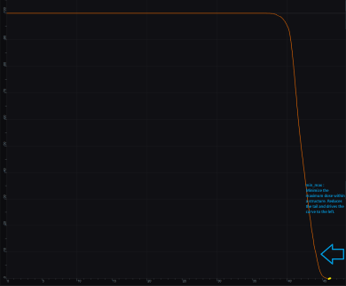
- min_max: Minimize the maximum dose within a structure (drive dose down)
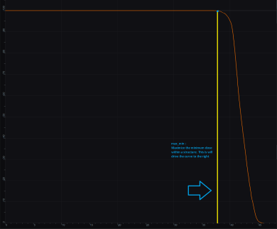
- max_min: Maximize the minimum dose within a structure (drive dose up)
- min_mean: Minimize the mean dose within a structure (drive dose down)
- max_mean: Maximize the mean dose across the structure (drive dose up)
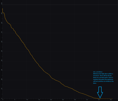
- min_overdose: Minimize the high dose within a structure
- Dose will be driven down only until the specified limit is reached (this is often more relevant that min_max, since it may not be beneficial to continue minimizing beyond a certain dose level)
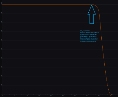
- min_underdose: Minimize the low dose within a structure
- Dose will be driven up only until the specified limit is reached (this is often more relevant that max_min, since it may not be beneficial to continue maximizing beyond a certain dose level)
Working with Objectives
- Open the Objectives/Optimizer sub-block contained in the Optimization block
- Choose a structure to which you wish to apply objectives
- Check the boxes to activate the desired objectives for the structure and then set the dose level if applicable
Once all the Objectives have been set, the user is ready to run the MCO solver, which is performed in the Objectives/Optimizer block.


